PIN Designation Function
14 Uni-I 10 Universal input 10, configurable:
•
S
tatic control input E2
•
Universal input: EDM (external device monitoring, OSSD pair
2), sleep mode, restarting the device, pausing event recording
15 Uni-O 01 Universal output 1: contamination, error, reset required (OSSD pair
1), monitoring result
16 Uni-O 02 Universal output 2: contamination, error, reset required (OSSD pair
2), monitoring result
17 0VDC Voltage for inputs and outputs (0VDC)
1)
1)
If at least one connection of the female connector XG1 is used, this 0V connection must be connected in
t
he control cabinet to 0VDC of the power supply unit using a low-impedance and star-point connection.
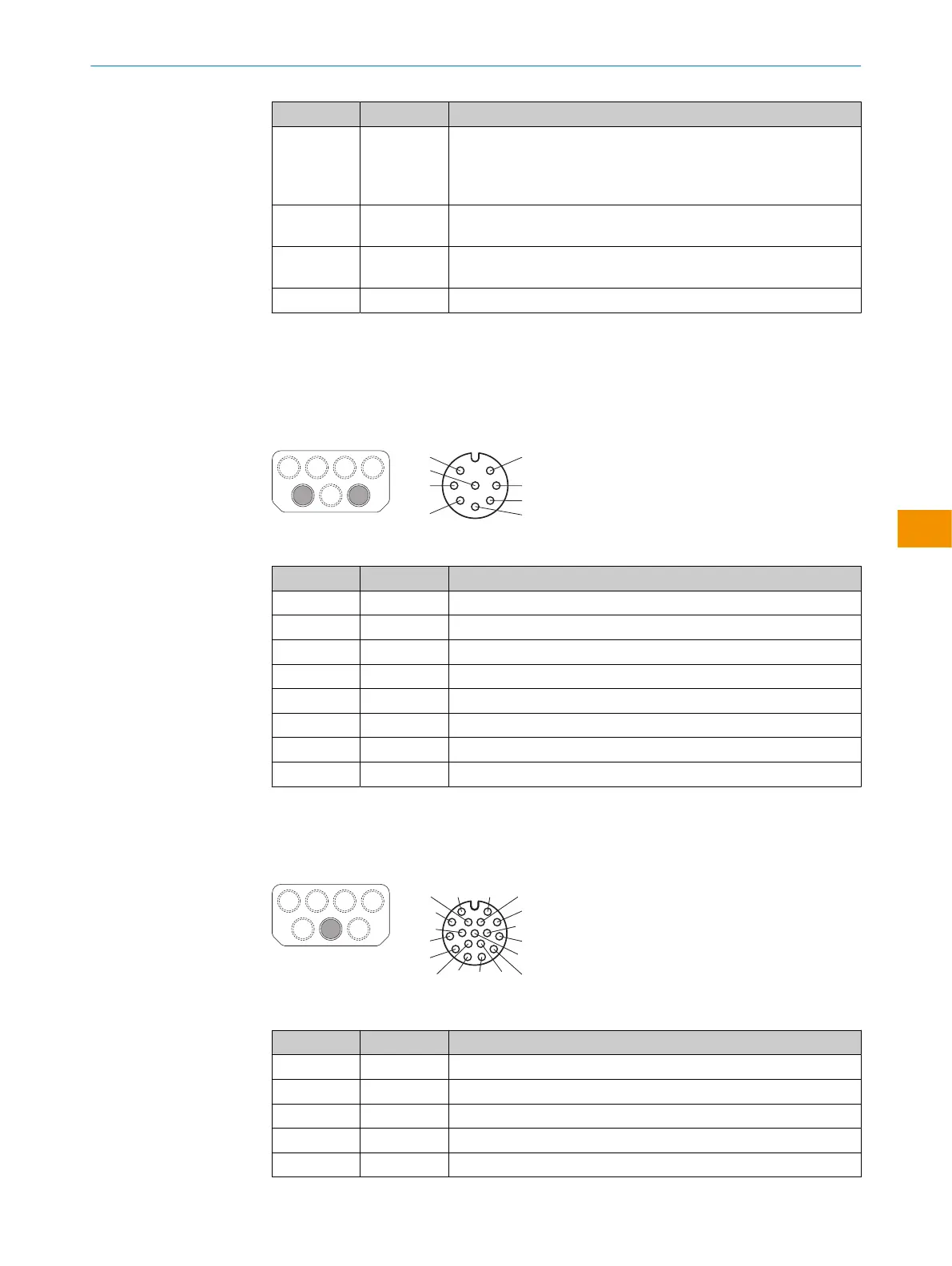
7.5 Dynamic control input (XG2, XG3)
Female connector, M12, 8-pin, A-coded.
Pin assignment for dynamic control input
PIN Designation Function
1 nc Not connected
2 Inc 0° Incremental encoder signal (0°)
3 nc Not connected
4 Inc 90° Incremental encoder signal (90°)
5 nc Not connected
6 nc Not connected
7 0V Inc Supply voltage for incremental encoder (0VDC)
8 24 V DC Inc Supply voltage for incremental encoder (+24VDC)
7.6 Local inputs and outputs 2 (XG4)
Female connector, M12, 17-pin, A-coded.
1 2
6
7 14
12
3
4
5
8
9
10
11
13
15
17
16
Pin assignment for local inputs and outputs 2
PIN Designation Function
1 OSSD 3.A OSSD pair 3, OSSD A
2 OSSD 3.B OSSD pair 3, OSSD B
3 OSSD 4.A OSSD pair 4, OSSD A
4 OSSD 4.B OSSD pair 4, OSSD B
5 nc Not connected
MOUNTING INSTRUCTIONS
8026187/1H7G/2022-10-19 | SICK M O U N T I N G I N S T R U C T I O N S | microScan3 Pro I/O
17
Subject to change without notice
en
 Loading...


