23
SICK MSL
8 007 653/09-04-01 Technical Description • MSL © SICK AG • Safety Systems • Germany • All rights reserved
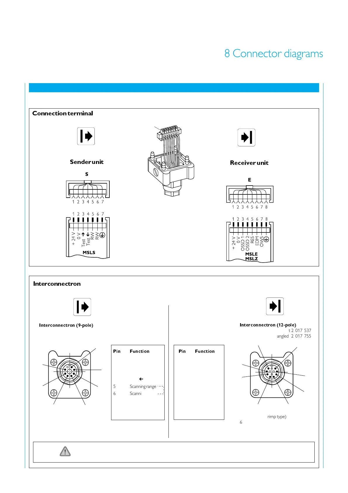
8 Connector diagrams
Connector pin-outs
Receiver unit
Sender unit
8 Connector diagrams
o
p
t
i
c
e
l
e
c
t
r
o
n
i
c
1
Interconnectron (12-pole)
Terminal chamber straight 2 017 537
angled 2 017 755
Interconnectron (9-pole)
Terminal chamber 2 017 536
Pin Function
1 + 24 V
20 V
3 Test
4 Test
5 Scanning range
6 Scanning range
7PE
Cable socket (crimp type)
6 008 441
When using Interconnectron connectors, only use safe, VDE 551 approved power supplies.
Pin Function
1+ 24 V
20 V
3 OSSD 1
4 OSSD 2
5 RES
6 EDM
7 OWS
8PE
5
1
7
6
4
3
2
Cable socket (crimp type)
6 008 440
Connection terminal
Interconnectron