26
SICK MSL
8 007 653/09-04-01 Technical Description • MSL © SICK AG • Safety Systems • Germany • All rights reserved
LEDs on sender unit must light up
Receiver unit
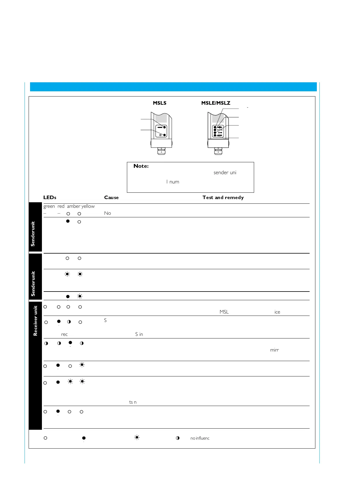
LEDs Cause Test and remedy
green red amber yellow
– – No power Check voltage
– – Sender inactive Change MSLS
Open circuit between terminals 3 and 4 Check passage
(test contact)
Device in LOCKOUT Operating voltage OFF/ON
(fault condition) Replace MSLS or contact SICK Service
– – No supply voltage Check voltage
– – 8/s 8/s Device in lockout Operating voltage OFF/ON
Replace MSLS or contact SICK Service
– – 1/s Break between terminal 3 and 4 (test contact) Check continuity
No supply voltage at MSLE/MSLZ Check voltage at MSLE/MSLZ
Replace MSLE or contact SICK Service
System misaligned Realign MSLE and MSLS
Receiver unit MSLE/MSLZ faulty Change MSLE/MSLZ
(no light received) Test input MSLS interrupted Check testing
System or corner mirror misaligned Realign system or corner mirror
Front screen of MSLE/MSLS/MSLZ Clean front screen and/or corner mirror
and/or corner mirror dirty
Exit window and/or corner mirror dirty Clean front screen and/or corner mirror
Device in LOCKOUT Operating voltage ON/OFF, if the green LED still
remains unlit, change MSLE/MSLZ
or contact SICK Service
EDM contacts not operating Check NC relay k 1 and k 2
24 V DC permanently supplied at RES Check RES
input during operation Operating voltage OFF/ON
Sender unit
up to 9652xxxx
LED off
LED flashing
LED no influence
yellow
amber
yellow
amber
red
green
9 Diagnosis elements
9 Diagnosis elements
LED illuminated
Sender unit
from. 9652xxxx
Note:
There are two LED functions of the sender unit:
‡ up to serial number 9 652 xxx and
‡ from serial number 9 701 xxx