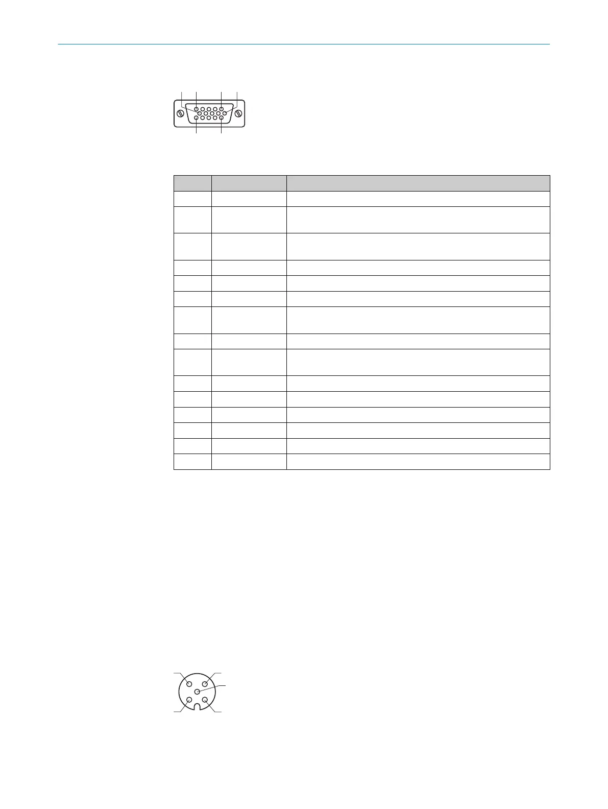
SERIAL, I/O connection
Figure 4: Female connector, D-SUB, 15-pin, coded
Pin Signal Function
1 DC 24Vout Supply voltage OUT
2 TxD from SERIAL
1
RS-232, sender 1
3 RxD from SERIAL
1
RS-232, receiver 1
4 Digital Out 2 Digital output 2 (sensor 2)
5 GND Supply voltage ground
6 nc -
7 TxD from SERIAL
2
RS-232, sender 2
8 nc -
9 RxD from SERIAL
2
RS-232, Receiver 2
10 CAN H CAN bus
1)
11 CAN L CAN bus
1)
12 Digital In 1 Digital input 1 (result 1)
13 Digital In 2 Digital input 2 (result 2)
14 Digital Out 1 Digital output 1 (sensor 1)
15 nc –
1)
The SIM800 does not offer any CAN functionality of its own. A CAN connection can, however, be
established between the "Power” port and the "SERIAL, I/O” port for CAN-capable sensors.
Max. 2A output for supply voltage connection (internal fuse, not accessible)
Digital outputs:
•
Max. output 100mA., current limited
•
Short-circuit protected
•
Push-pull switch
•
Min. high output logic level: V
CC
-2V
•
Max. low output logic level: 2V
Digital inputs:
•
High input logic level: 8V ... 30V
•
Low input logic level: 0V ... 4V
INPUT connection (digital input)
Figure 5: Female connector, M12, 5-pin, A-coded
ELECTRICAL INSTALLATION 6
8028935//2023-09-26 | SICK O P E R A T I N G I N S T R U C T I O N S | SIM800
17
Subject to change without notice