6.3 Overview of connections
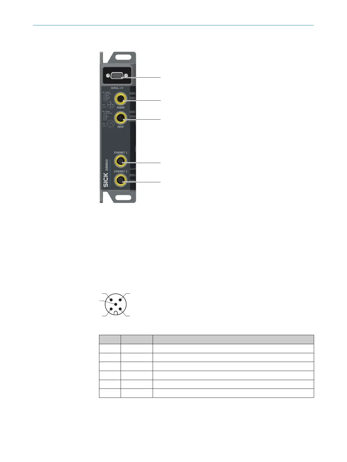
Figure 2: SIM800 connection overview
1
SERIAL, I/O: Connection for sensors and controller
2
POWER: Voltage supply
3
INPUT: Digital input
4
ETHERNET 1: Ethernet port
5
ETHERNET 2: Ethernet port
6.4 Pin assignment
POWER connection (supply voltage)
Figure 3: Male connector, M12, 5-pin, A-coded
Pin Signal Function
1 DC 24 Vin Supply voltage IN
2 CAN L CAN bus
1)
3 DC 0 Vin Supply voltage ground
4 CAN H CAN bus
1)
5 nc –
– – Shield
1)
The SIM800 does not offer any CAN functionality of its own. A CAN connection can, however, be
established between the "Power” port and the "SERIAL, I/O” port for CAN-capable sensors.
Observe the requirements for the design of overcurrent protective devices according to
EN61010, "Technical data", page 24.
6 ELECTRICAL INSTALLATION
16
O P E R A T I N G I N S T R U C T I O N S | SIM800 8028935//2023-09-26 | SICK
Subject to change without notice