2
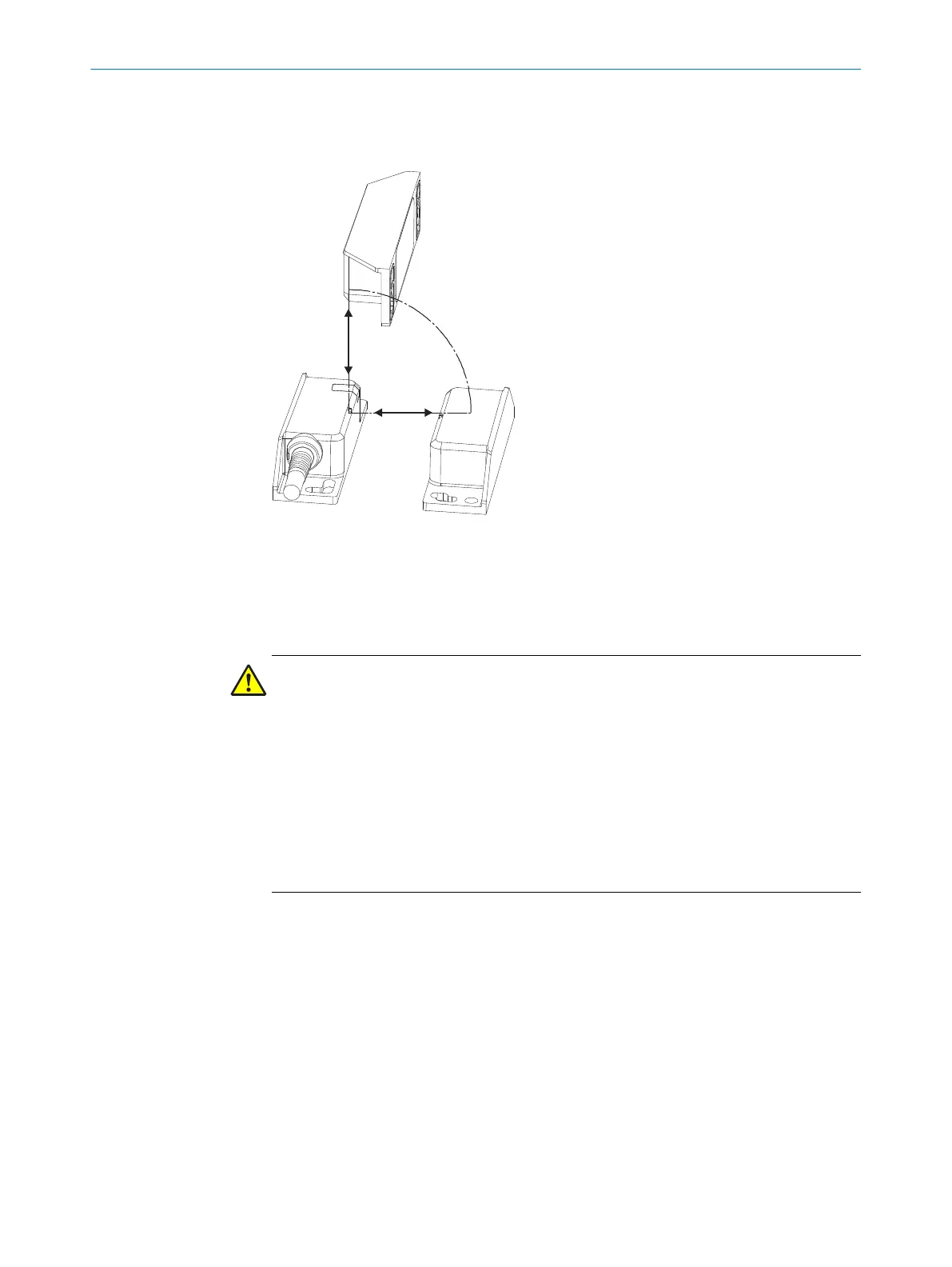
Side deviation in mm
3
Distance to sensor surface in mm
Figure 2: Approach directions
b
If nece
ssary, attach an additional protective stop for the moving part of the protec‐
tive device.
b
Observe the maximum tightening torque of 2.2 Nm for mounting the sensor and
actuator.
DANGER
Ob
serve the following safety notes:
b
The sensor and actuator must not be used as a mechanical stop.
b
Prevent manipulation such as adjustment, disassembly or circumvention of the
device which prevents proper functioning in any way. Otherwise serious injuries or
even death could be the result.
b
The integrity of the safety system can be endangered if there are available replace‐
ment actuators (risk of manipulation). This can lead to injuries or death, property
damage or economic loss. Arrange for appropriate monitoring, work processes or
alternative protective measures to regulate the use and availability of these
replacement actuators.
Mounting of several safety switches
b
W
hen several safety switches are mounted, observe the prescribed minimum dis‐
tance of 50 mm between the individual systems in order to avoid mutual interfer‐
ence.
MOUNTING 4
8023286/15V1/2019-11-22 | SICK O P E R A T I N G I N S T R U C T I O N S | TR4 Direct Rectangular
11
Subject to change without notice