NOTE
T
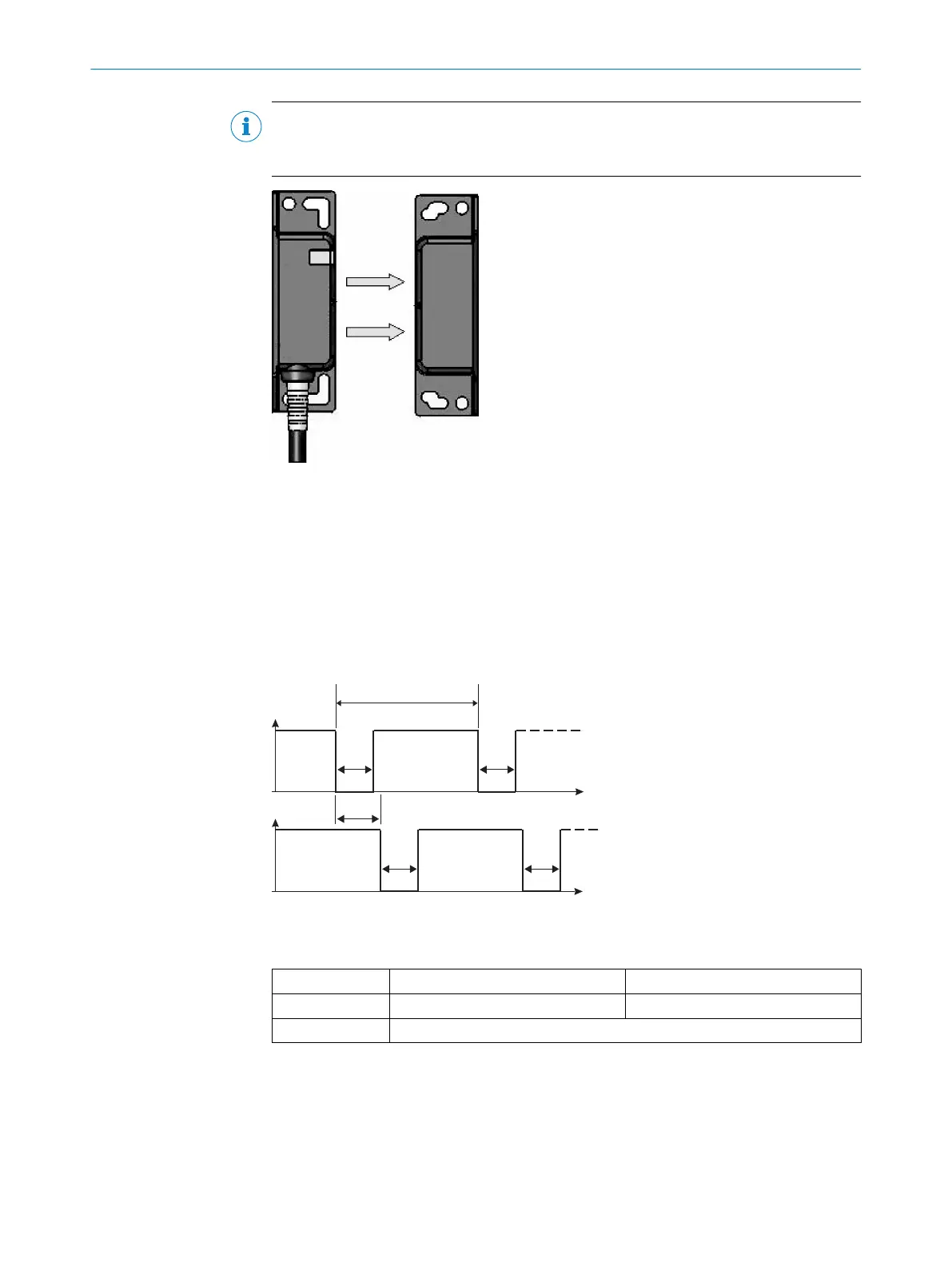
he magnetic holding force is measured from the front side of the actuator to the front
side of the sensor. see figure 9).
Figure 9: Area for measuring the
ma
gnetic holding force
9.2 Course of the OSSD test over time
The safety locking device tests the OSSDs for self-diagnosis at regular intervals. To
do t
his, the safety locking device switches each OSSD briefly to the OFF state and
checks whether this channel is voltage-free during this time.
Make sure that the machine’s control does not react to these test pulses and the
machine does not switch off.
Figure 10: Course of the OSSD test over time
1
Usually every 20 ms.
1
Test pulse interval About every 45 ms
2
Test pulse width 450 μs
3
Test pulse deviation
TECHNICAL DATA 9
8023286/15V1/2019-11-22 | SICK O P E R A T I N G I N S T R U C T I O N S | TR4 Direct Rectangular
25
Subject to change without notice