Sensor
A
ctuator
Polycarbonate
Polycarbonate
1)
At least one of the two OSSD outputs is safely switched off during the response time.
2)
The risk time is the time needed to detect external faults. External errors affect the OSSD safety outputs
(shor
t-circuit to an OSSD safety output and cross-circuit between the two safety outputs). At least one of
the two OSSD outputs is safely switched off during the risk time. Note that the time for the safety require‐
ment (closing the protective device again) must be longer than the risk time.
3)
After the supply voltage has been switched on, the OSSD outputs and the application diagnostic output
ar
e at Low potential during the time delay before availability. The time specified applies to one sensor; in
a cascade, 0.1 s must be added per sensor.
4)
Length of cable and cable cross-section change the voltage drop depending on the output current (R
max
=
14.5 Ω).
Application-related high input loads and long cable lengths may result in functional limitations of the
device.
Table 8: Outputs
2 OSSDs 2 × PNP, 0.2 A max., protected against short-
cir
cuits and overloads
Application diagnostic output 1 × PNP, 0.2 A max., protected against short-
circuits and overloads
Switching voltage
ON state 20.4 V DC … 26.4 V DC
OFF state 0 … 2 V DC
Voltage drop compared to supply voltage V
S
< 1.5 V DC
Table 9: Ambient environment
Ambient operating temperature –25 °C … +70 °C
Relative humidity 5% … 95%
Enclosure rating IP67, IP69K
Vibration resistance 3.5 mm / 10 … 55 Hz (EN 60 068-2-6)
Shock resistance 30 g, 11 ms (EN 60068-2-27)
EMC In accordance with IEC 61000, IEC 61326-1,
IE
C 6100-6-7, IEC 60497-1
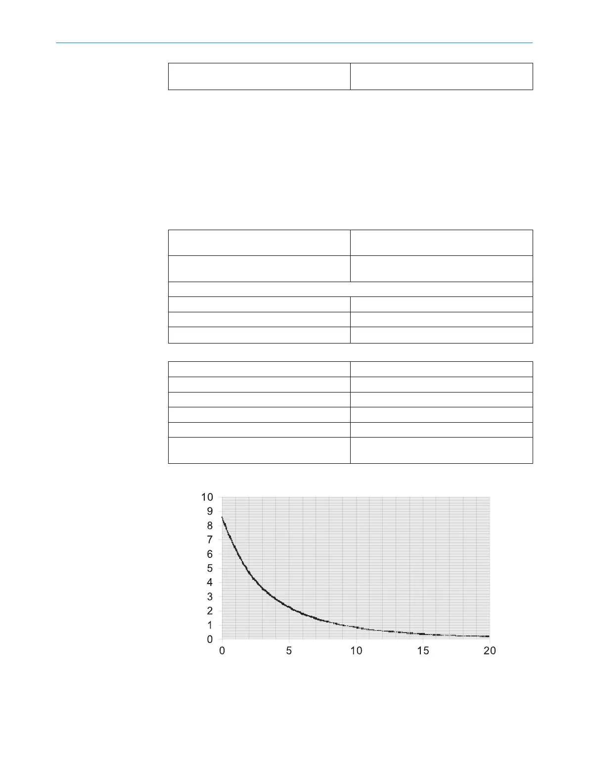
Magnetic holding force
Figure 8: Magnetic holding force diagram (TR4-SFxxxx only)
1
Distance [mm]
2
Force (N)
9 TECHNICAL DATA
24
O P E R A T I N G I N S T R U C T I O N S | TR4 Direct Rectangular 8023286/15V1/2019-11-22 | SICK
Subject to change without notice