Pin Signal Function
2 V
S
Supply voltage
3 CAN L CAN bus (IN/OUT)
4 CAN H CAN bus (IN/OUT)
5 TD+ (RS-422/485), host Host interface (sender+)
6 TD– (RS-422/485), host
TxD (RS-232), host
Host interface (sender-)
7 TxD (RS-232), Aux Aux interface (sender)
8 RxD (RS-232), Aux Aux interface (receiver)
9 SensGND Digital input ground
10 Sensor 1 Digital input 1
11 RD+ (RS-422/485), host Host interface (receiver+)
12 RD– (RS-422/485), host
RxD (RS-232), host
Host interface (receiver–)
13 IN/OUT 3 Digital input/Digital output 3 (configurable)
14 IN/OUT 4 Digital input/Digital output 4 (configurable)
15 Sensor 2 Digital input 2
16 IN/OUT 5 Digital input/Digital output 5 (configurable)
17 IN/OUT 6 Digital input/Digital output 6 (configurable)
– – Shield
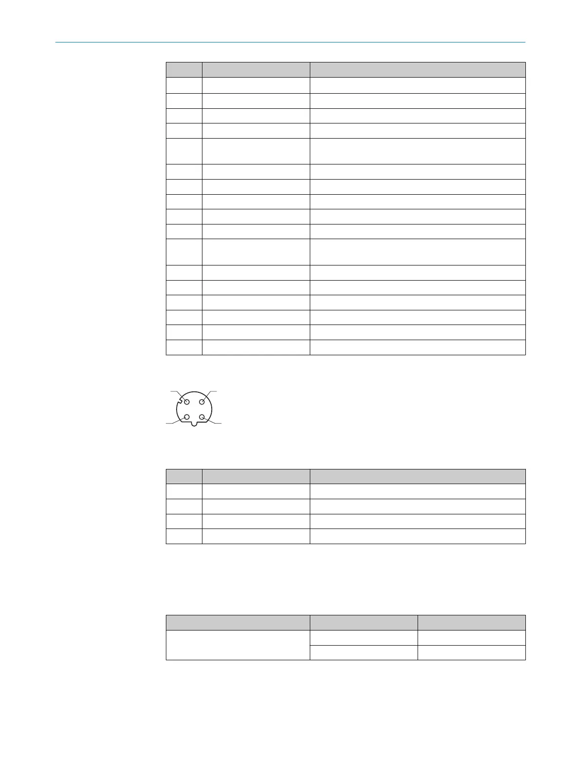
“Ethernet” connection
Figure 19: M12 female connector, 4-pin, D-coded
Table 6: Pin assignment of the “Ethernet” connection
Pin Signal Function
1 TD+ Sender+
2 RD+ Receiver+
3 TD– Sender–
4 RD– Receiver–
6.5 Connecting the device
6.5.1 Using the optional connection modules CDB and CDM
Table 7: Possible combinations of device and connection modules
Connection on the device Connection modules Connection cable
Male connector, M12, 17-pin, A-
coded
CDB650-204 Cable 1:1
1)
CDM420-0006
2)
Adapter cable
3)
1)
Connection cable 1:1 (female connector, M12, 17-pin, A-coded / male connector, M12, 17-pin, A-coded).
2)
CDM420-0007: for connecting 2 devices.
3)
Adapter cable (female connector, M12, 17-pin, A-coded / male connector, D-Sub-HD, 15-pin).
6 ELECTRICAL INSTALLATION
34
O P E R A T I N G I N S T R U C T I O N S | InspectorP621 8024439//2019-06 | SICK
Subject to change without notice
 Loading...

