NOTICE
Faults during operation and device or system defects!
Incorrect wiring may result in operational faults and defects.
■
Follow the wiring notes precisely.
The protection class stated in the technical data is achieved only with screwed plug con‐
nectors or protective caps.
Configure the circuits connected to the device as ES1 circuits or as SELV circuits (SELV
= Safety Extra Low Voltage). The voltage source must meet the requirements of ES1
and PS2 (EN 62368-1) or SELV and LPS (EN 60950-1).
Protect the device with an external slow-blow fuse at the beginning of the supply cable.
Connect the connecting cables in a de-energized state. Do not switch on the supply volt‐
age until installation is complete and all connection work on the device and controller
has been finished.
Perform all connection work only at ambient temperatures above 0 °C.
Connect the device only to the permissible supply voltage, see "Connecting the supply
voltage", page 35.
Wire cross-sections in the supply cable from the customer’s power system must be
implemented in accordance with the applicable standards.
In the case of open end cables, make sure that bare wire ends do not touch. Wires
must be appropriately insulated from each other.
Wire cross-sections of the data and switching signal cables have to also be designed in
accordance with the applicable national standards.
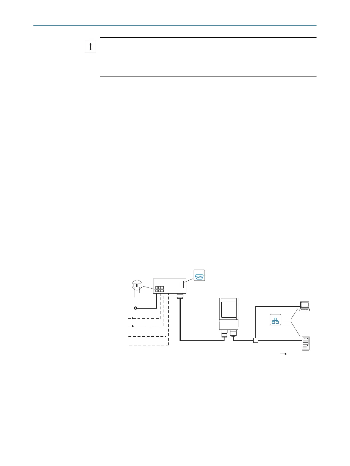
6.3 Connection diagrams
6.3.1 Connection principle for operation mode
"Ethernet"
(Host 2)
Input 2 ß
Input 1 à
Input/output 4 9
Input/output 3 8
InspectorP621
Connection module 2
SerialSerial
Image display
SICK AppStudio
Web UI
SICK AppStudio
Web UI
"Power/Serial Data/
CAN/I/O"
(Aux 1, Host 1)
...
...
1
2
V
S
1
GND
HOST
PC
Further data
processing
"Ethernet" (Aux 2,
image transfer) 3
V
S
EthernetEthernet
Cable 7
4
6
Result 5
Figure 16: Connection block diagram
1
Supply voltage V
s
2
Connection module CDB650-204 or CDM420-0006
3
Ethernet-Aux port (image transmission)
4
Image display
5
Result
6
Further data processing
6 ELECTRICAL INSTALLATION
32
O P E R A T I N G I N S T R U C T I O N S | InspectorP621 8024439//2019-06 | SICK
Subject to change without notice
 Loading...

