Device 1
CDB650-204
Load (e.g. PLC) 4
Cable 3
B
1
.
.
.
D
22
GND
5Shield
U
IN
*V
S
GND
V
out
Result A
GND
B
1
2 2
For inductive load: 6
3
1
7
2
6
5
4
8
13
14
17
15
9
10
12
16
11
3
1
7
2
6
5
4
8
13
14
17
15
9
10
12
16
11
RES/OUT C
8 7
2
5
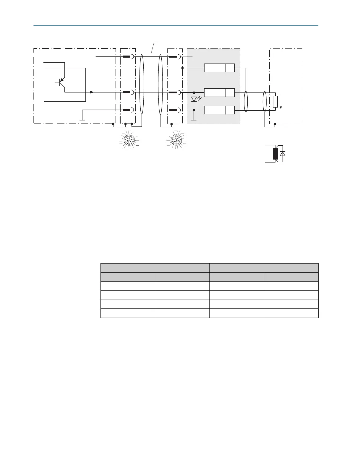
Figure 32: Wire digital outputs "IN/OUT 3" to "IN/OUT 6" of the device in the CDB650-204 connection module
1
Device
2
Supply voltage V
S
3
Connection cable 1:1 (female connector, M12, 17-pin, A-coded/male connector, M12, 17-pin, A-coded)
4
Load (e.g. PLC)
5
Output voltage V
out
6
With inductive load: see note
7
Connection module: female connector, M12, 17-pin, A-coded
8
Device: male connector, M12, 17-pin, A-coded
Table 16: Assignment of placeholders to the digital outputs
Device CDB650-204
Output A Pin B Signal C Terminal D
IN/OUT 3 13 RES/OUT 1 20
IN/OUT 4 14 RES/OUT 2 21
IN/OUT 5 16 RES/OUT 3 50
IN/OUT 6 17 RES/OUT 4 51
13.4 Connection diagrams of connection module CDM420-0006
13.4.1 Connection of the device to CDM420-0006
13 ANNEX
62
O P E R A T I N G I N S T R U C T I O N S | InspectorP621 8024439//2019-06 | SICK
Subject to change without notice
 Loading...

