â
Example of alternative connection module
CDM420-0006
CDM420-0006: An adapter cable (female connector, M12, 17-pin, A-coded / male con‐
nector, D-Sub-HD, 15-pin) is required to connect the device
NOTE
Control the CAN data interface in the device with the API functions. In order to activate
the CAN data interface, use an installed SensorApp which contains this function.
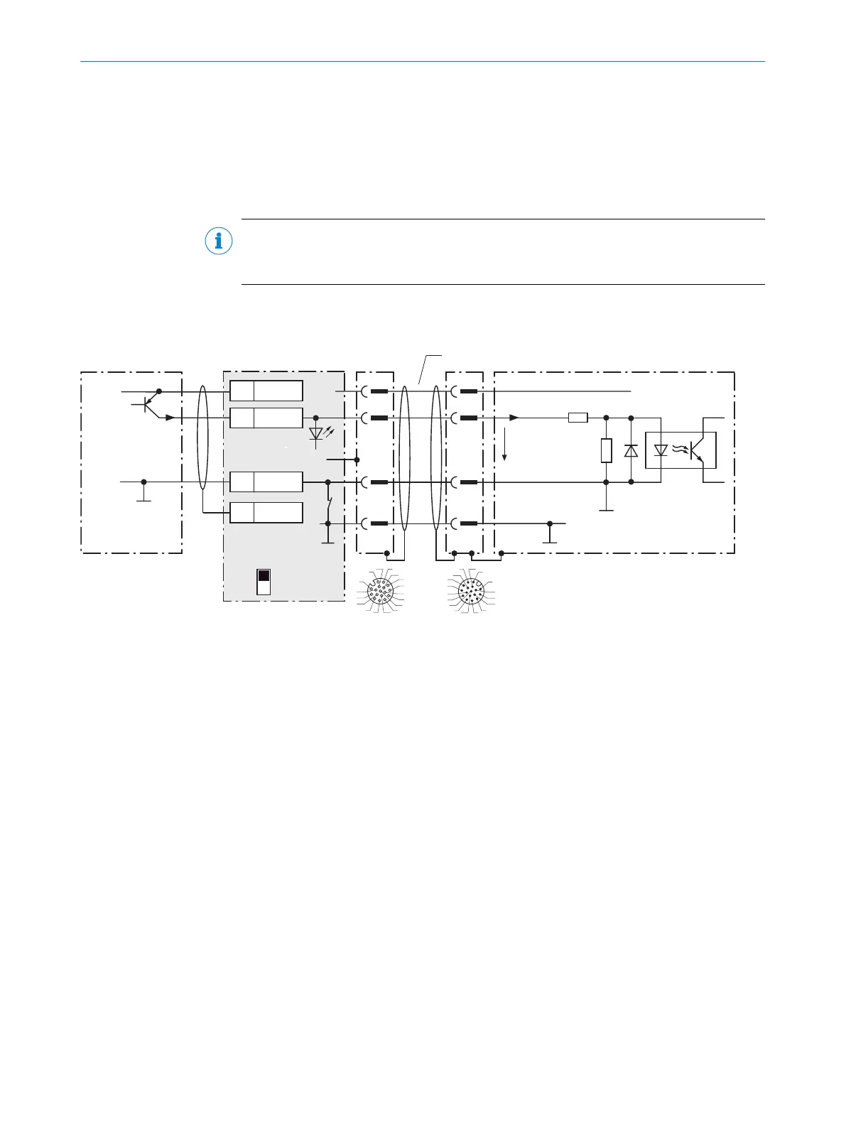
13.3.7 Wiring digital inputs of the device in the CDB650-204
Device 3CDB650-204
PNP sensor 8
V
S
V
S
V
S
GND
SensGND
3.32 K
6.64 K
Sensor D
V
in
C
99
2
1
C
2
1
12
SGND
6
Shield
11
U
IN
*
A
Out
U
IN
*
GND
S3
Trigger sensor 1
E.g. photo-electric
switch 7
ON
OFF
S3 : SGND-GND
Shield
GND
.
.
.
SensGND
GND
3
1
7
2
6
5
4
8
13
14
17
15
9
10
12
16
11
3
1
7
2
6
5
4
8
13
14
17
15
9
10
12
16
11
6 5
Cable 2
SENS/IN B
4
9
Figure 31: Trigger sensor supplied with power by connection module CDB650-204
1
Trigger sensor
2
Connection cable 1:1 (female connector, M12, 17-pin, A-coded/male connector, M12, 17-pin, A-coded)
3
Device
4
Input voltage V
in
5
Device: male connector, M12, 17-pin, A-coded
6
Connection module: female connector, M12, 17-pin, A-coded
7
e.g. photoelectric sensor
8
PNP sensor
9
Supply voltage V
S
13.3.8 Wiring digital outputs of the device in the CDB650-204
ANNEX 13
8024439//2019-06 | SICK O P E R A T I N G I N S T R U C T I O N S | InspectorP621
61
Subject to change without notice
 Loading...

