„V
S
”
“Host 1”
“Aux 1”
“Result 2”
“Result 1”
“CAN”
“Sensor 2”
“Sensor 1”
“AUX”
CAN bus
“Result 1”
“Result 2”
PLC
“External output 2
CDM420-0006
Connection module 6
“Host 1”
“Aux 1”
RS-232
HOST/PLC
Further data
processing 8
PC
Configuration
Diagnostics
Image display
Interfaces 3
Device 2
“Ethernet” (Host 2/Aux 2), Image transfer 5
“USB” (Aux 3) 4, Image transfer 5
RS-232/RS-422
Ethernet
USB
“Host 2”
Ethernet
“Aux 2”
“Aux 3”
“Sensor 2”
“Sensor 1”
“External input 2”
“External input 1”
CMC600
1
ã
â
V
S
ß
= á
“External output 1”
à 9
7
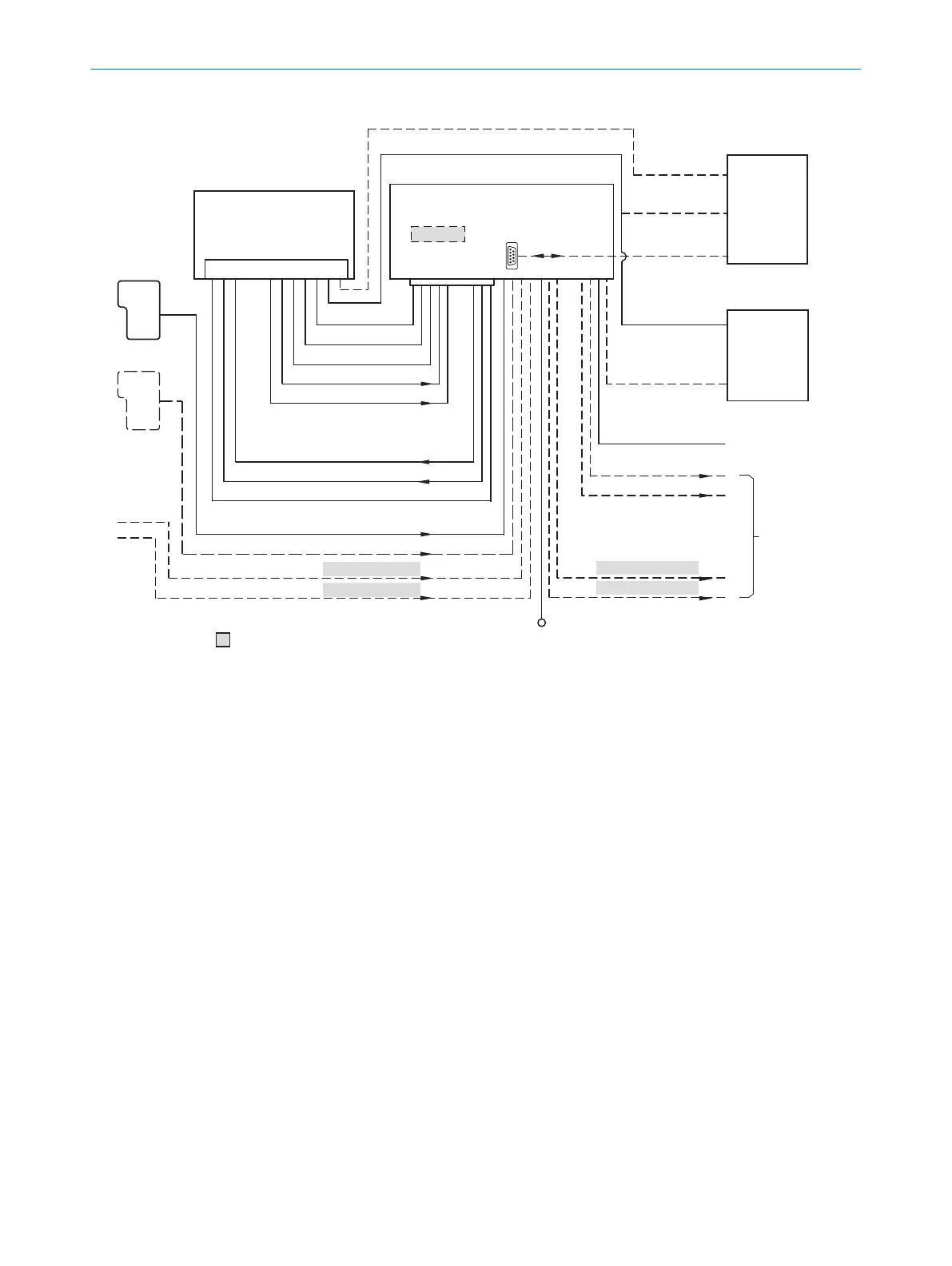
Figure 33: Connection of the device to peripherals via CDM420-0006 (overview)
1
External trigger sensor
2
Device
3
Interfaces
4
USB interface (not supported)
5
Image transmission
6
Connection modules
7
Configuration, diagnostics or image display
8
Data further processing
9
External digital outputs (not supported)
ß
Supply voltage V
S
à
External digital inputs (not supported)
á
Optional CMC600 parameter cloning module to use the external digital inputs and outputs of the device (not sup‐
ported).
13.4.2 Wiring overview of the CDM420-0006
ANNEX 13
8024439//2019-06 | SICK O P E R A T I N G I N S T R U C T I O N S | InspectorP621
63
Subject to change without notice
 Loading...

