3 Sensing range setting
Sensor with potentiometer: open the sensor cover and protective hood, make sure that no
dirt has gotten into the sensor.
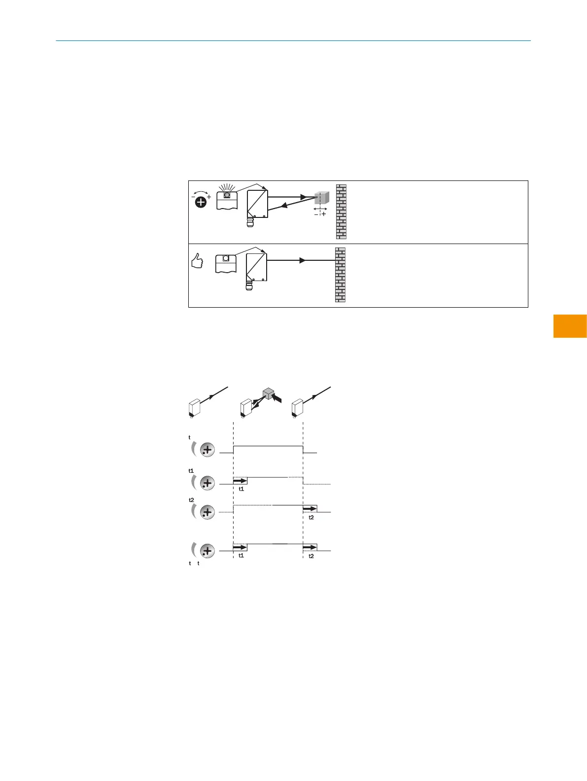
The sensing range is adjusted with the potentiometer (type: without stop). Clockwise
rotation: sensing range increased; counterclockwise rotation: sensing range reduced. We
recommend placing the object within the sensing range, e.g. see table 8. Once the sensing
range has been adjusted, the object is removed from the path of the beam, which causes
the background to be suppressed and the switching output to change [see figure 5 and
figure 6].
Table 8: Einstellung Schaltabstand
The sensor is adjusted and ready for operation.
4 Time function setting
WT24-2: t0= no time delay, t1 = time delay, t2 = time delay; for -2R: 0 = relay deactivated,
1 = relay active. Time delay selector switch can be set on the device according to the
following graphic.
Time stages: 0.5 ... 10s can be adjusted.
0
1 2
+
0.5 ... 10 sec.
0.5 ... 10 sec.
0.5 ... 10 sec.
Figure 7: Time functions
8 Devices with special features
WT24-2xx2x / -2xx5x: with static front-screen heating for use in environments with
gradual temperature changes within the +5°C ... +15°C range.
WT24-2R210S03: with mounting bracket (2016754)
WT24-2B420S08: sensing range max.: 30…3000mm on white (90% remission), with
timer unit: adjustable 0.6…1.3sec
WT24-2V210S09: preset to dark switching, with mounting bracket (2016754)
WT24-2V540S10: glass front screen
OPERATING INSTRUCTIONS
8008784.1DMA/2022-07-12 | SICK O P E R A T I N G I N S T R U C T I O N S | WT24-2
13
Subject to change without notice
en