Test input
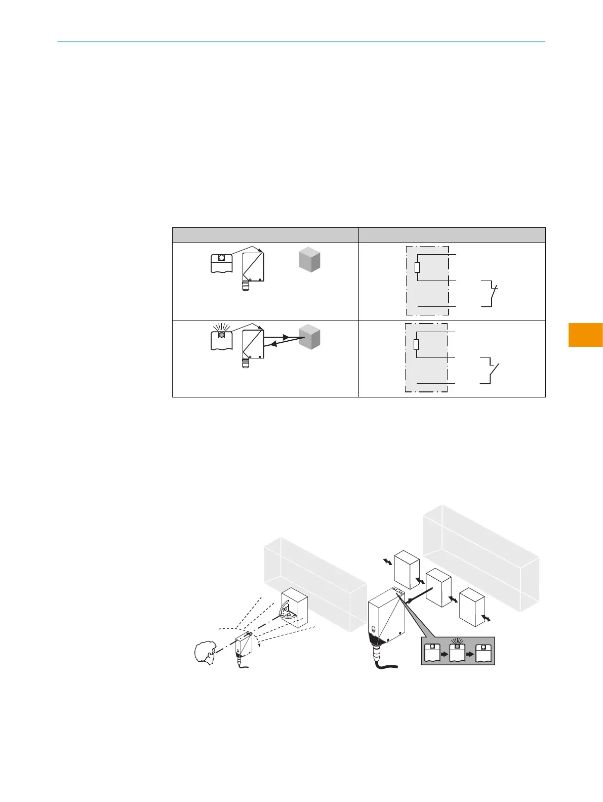
Test input: the WT24-2B/-V sensors feature a test input (“TI” or “Test” on the connec‐
tion diagram [see „WT24-2Bxxx, WT24-2Vxxx“, page 8 and see table 7]), which can
be used to switch the sender off and, therefore, check that the sensor is functioning
correctly: if female cable connectors with LED indicators are used, you have to ensure
that the TI is assigned accordingly.
If an object is detected, activate the test input (see the connection diagram [see
„WT24-2Bxxx, WT24-2Vxxx“, page 8 and see table 7], PNP: TE → M). The send LED is
shut down or no object being detected is simulated. Use the following table to check the
function. If the switching output fails to behave in accordance with the following table,
check the application conditions. See section Fault diagnosis.
Table 7: Test
Test
7 Commissioning
1 Alignment
WT24-2Xx1x, -2Xx2x: align sensor on object. Select the position so that the infrared light
(not visible) hits the center of the object. The correct alignment can only be detected via
the LED indicators. See figure 3 and figure 4. You must ensure that the optical opening
(front screen) of the sensor is completely clear.
Figure 3: Alignment Figure 4: Alignment 2
OPERATING INSTRUCTIONS
8008784.1DMA/2022-07-12 | SICK O P E R A T I N G I N S T R U C T I O N S | WT24-2
11
Subject to change without notice
en