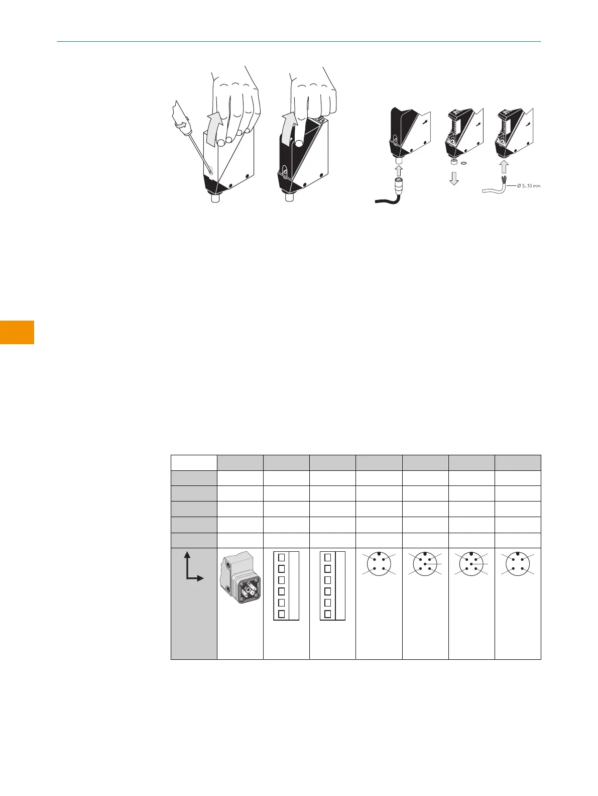
Figure 1: Opening the sensor Figure 2: Electrical connection
Only apply voltage/switch on the power supply once all electrical connections have
been established.
Explanation of the connection diagram (Tables 2-7) which are divided up into DC and
AC/DC devices:
Alarm = alarm output (see table 2 and Additional functions)
n. c. = not connected
NC = normally closed
NO = normally open
Q / Q = switching outputs
TE/Test = test input (see table 2 and table 7)
5.1
WT24-2Bxxx, WT24-2Vxxx
U
B
: 10 . 30VDC, see „Technical data“, page 15
Table 2: DC
WT24-2 B3x3 B2x0 V2x0 B4x0 V5x0 V510S15 B410S25
1 + (L+) + (L+) + (L+) + (L+) + (L+) + (L+) + (L+)
2 - (M) - (M) - (M) Test Test Alarm n. c.
3
Q/Q
- Alarm - (M) - (M) - (M) - (M)
4 -
Q/Q Q/Q Q/Q Q/Q Q/Q Q/Q
5 - Test Test - Alarm Test -
I
N
= 4A
0.14 ...
1.5 mm
2
I
N
= 4A
0.14 ...
1.5 mm
2
I
N
= 4A
OPERATING INSTRUCTIONS
8
O P E R A T I N G I N S T R U C T I O N S | WT24-2 8008784.1DMA/2022-07-12 | SICK
Subject to change without notice
en