3ZX1012-0RB22-1CA1 5
2.3 Sensor circuit wiring
2.4 Sensor circuit short-circuit detection
This corresponds to the following typical cable lengths:
2.5 Short-circuit protection according to EN 60947-4-1 for
utilization category 2
The short-circuit protection must be adopted from the separate over-
current protection devices.
2.6 Cable protection
2.7 Automatic RESET
2.8 User test
The tests according to EN 60079-17 can be carried out together with
the user test. This test includes a complete functional test. All four test
phases must be carried out as described in the following table. The
individual test phases include the LED test (1), the configuration test
(2), the internal test with current measurement (3) and the relay test
(4). The measured current values must be checked!
The measured current values and the correct opening and closing of
the relay contacts (test phase 4) must be checked!
All protective functions remain activated during the test. A tripping
operation or a warning results in abortion of the test!
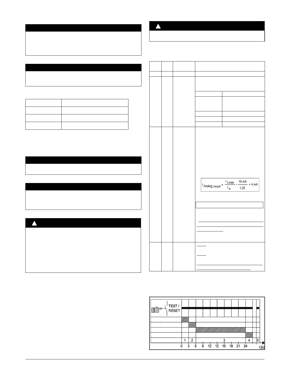
To start the test, press the TEST / RESET button for t > 1 s.
*) When the three red LEDs flicker, relay switch-off has been initiated.
Up to this point in time, it is possible to abort the user test without
switching off the relays.
The following graphic shows an overview of the temporal course:
NOTICE
The lines in the measuring circuit must be laid as separate control
lines. The use of motor feeder lines or other main power lines is
not permissible. Shielded control cables must be used if extreme
inductive or capacitive interferences from high tension cables run-
ning in parallel are to be expected.
NOTICE
To ensure reliable functioning of the short-circuit protection, the
line resistance in the thermistor circuit (when the thermistor is
short-circuited) must not exceed 10 Ω!
Cable cross section Cable lengths at the thermistor input
2,5 mm
2
2x250m
1,5 mm
2
2x150m
0,5 mm
2
2x50m
NOTICE
In combination with other contactors please observe the respec-
tive maximum contactor protection for utilization class 2.
NOTICE
Excessive surface temperatures of the cables and lines must be
prevented by dimensioning the cross sections accordingly.
An adequate cable cross section must be chosen for heavy start-
ing - CLASS20 and CLASS30 - in particular.
CAUTION
When the 3RB22 / 3RB24 is in the "Automatic RESET" mode, the
reset is carried out automatically at the end of the cooling time
without the RESET button being pressed. In this case, an addi-
tional ON button is necessary to prevent the motor from automati-
cally starting up again after being tripped. If, in this case, the
3RB22 / 3RB24 is used without thermistor protection, the motor
can only be connected by a specialist.
The "Automatic RESET" mode may not be used in applications in
which an unexpected motor restart could lead to personal injury or
damage to property.
CAUTION
This test must be carried out by a specialist familiar with the stan-
dards stated!
Test
phase
Durati
on
Description Comment
1 3 s LED test The user checks whether all LEDs are flashing
2 3 s Configuration
test
Flickering LEDs indicate that the respective
functions are activated. The user checks the
active functions
LED Function
3RB22: READY
3RV24: Device/
IO-Link
Automatic reset active
GND-Fault Ground fault evaluation
THERMISTOR Thermistor activated
OVL Overload warning active
3 18 s Internal test The system is executing internal tests. The
analog output is permanently activated
throughout the test period. The user must
compare the maximum motor current of the 3
phases with the current at the analog output.
The following must apply:
• the effective current must be between 30% and
125% of the nominal current
• the maximum motor current leads to an “ideal”
analog current I
Analog,target
of
• the actual measured analog current
I
Analog, actual
must be within the range
0.9 * I
Analog,target
≤ I
Analog,actual
≤ 1.1 *
I
Analog,target
• Correct functioning cannot be guaranteed
if the measured current does not fall within
these tolerances.
The LEDs show the running time (see the
following graphic).
4 Relay test
*)
3RB22
: The system must switch off outputs 95 /
96 and 05 / 06.
3RB24
: The system must switch off outputs 95 /
96 and 95/ 98.
Correct functioning cannot be guaranteed
if the output contacts do not open!
 Loading...