Communication System Manual 3WN6 Circuit-Breakers
Copyright Siemens AG 1998. All rights reserved. Version1.0 (05/98)
48
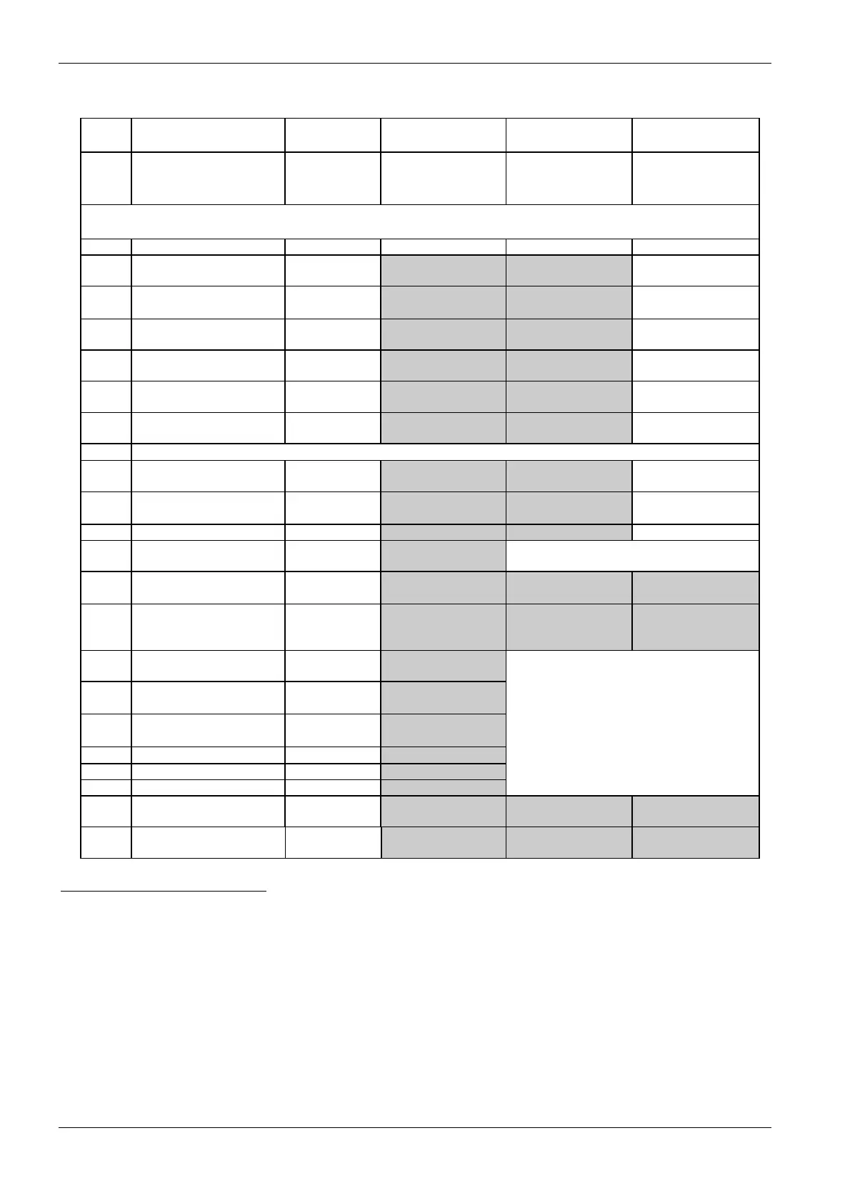
T-Nr. Designation Message
address
Value range Value range Value range
1:x Setting values/
Protection
parameters
Releases
N and P
Releases
H and J/K
Releases
D and E/F
Note: Settable values/functions are highlighted in grey. The incremental settings for these values are
given on the next page.
x =
61 "a" release setting
current I
r
782, 1, 0, 22, 0 40 - 100 % I
n
(A) 40 - 100 % I
n
(A) 0; 40 - 100 % I
n
(A)
64 Time-lag class T
c
(trip
class)
38) 39)
782, 4, 0, 0, 0 0; 20 - 300
(0.1 s)
0; 20 - 300
(0.1 s)
20 - 300
(0.1 s)
65 "z" release setting
current I
d
782, 5, 0, 22, 0 200 - 40000 A 50 % I
n
- 12 I
n
(A) 125 % I
r
-12 I
r
(A)
66 "z" release delay t
d
782, 6, 0, 4,
130
20; 80 - 400 ms 20; 80 - 400 ms 20; 80 - 400 ms
71 "g" release setting
current I
g
783, 1, 0, 22, 0 160 - 1200 A 20 % I
n
-1200 A 20 % I
n
- 60 % I
n
(A)
72 "g" release delay t
g
783, 2, 0, 4,
130
100 - 500 ms 100 - 500 ms 100 - 500 ms
Messages 71 and 72 are only available with releases E/F, J/K and P.
81 "N" release setting
current I
N
785, 1, 0, 22, 0 20 % - 100 % I
n
(A) 20 % - 100 % I
n
(A) 20 % - 100 % I
n
(A)
82 "n" release setting
current I
i
785, 2, 0, 22, 0 150 % I
n
-
50000/65000 A
40
)
0; 150 % I
n
-12 I
n
0; 150 % I
n
-12 I
n
83 "g/N" release type I
g
/N 785, 3, 0, 0, 0 0 - 5 0 - 1 0 - 1
84 I
n, ext
External current
transformer
785, 4, 0, 22, 0 315 - 3200 A
Message 84 for P release only
85 Release time or
alarm t
x
41
)
785, 5, 0, 4,
130
0; 1 - 15 s 0; 1 - 15 s 0; 1 - 15 s
93 Current phase imbalance 790, 3, 0, 24, 0 0; 50 %
(5 - 50 % with
Z=F05)
0; 50 % 0; 50 %
101 Voltage phase
imbalance
792, 1, 0, 24, 0 0; 5 - 50 %
102 Reversal of direction of
power flow
792, 2, 0, 9, 3 0; -2000 kW to
+2000 kW
42)
Messages 101 - 106 are only available
for releases
103 Overfrequency f> 792, 3, 0, 28, 0 0; 15 - 500 Hz
N and P in conjunction with
the communication module with
104 Underfrequency f< 792, 4, 0, 28, 0 0; 15 - 500 Hz
measuring functions (Z=F05).
105 Overvoltage U> 792, 5, 0, 21, 0 0; 100 - 1000 V
106 Undervoltage U< 792, 6, 0, 21, 0 0; 100 - 1000 V
107 Load shedding 792, 7, 0, 24, 0 0; 50 %-150 %
I
n
(A)
0; 50 %-150 %
I
n
(A)
0; 50 %-150 %
I
n
(A)
38)
These time vaues are in the range 2 - 30 s. The transferred values (20 - 300) must therefore be multiplied by 0.1.
39)
The function is deactivated with setting value "0". This also applies to T-Nr. 1:93, 1:101 - 108.
40)
Size I (<= 1600 A): 50 kA; Size II (> 1600 A): 60 kA.
41)
t
x
is the time delay for the trip or warning signal for setting values with T-Nr. 1:93, 1:101 - 108. If t
x
= 0, the delay = 0 s. The setting values with
T-Nr. 1:93, 1:101 - 108 can also be deactivated by setting the value as a parameter. With Z=F05, these setting values can be parameterized
as either a trip or a warning, see T-Nr. 1:111, OS1:2.
42)
Supply from below: >0; Supply from above: <0.
108 Load input 792, 8, 0, 24, 0 0; 50 %-150 %
I
n
(A)
0; 50 %-150 %
I
n
(A)
0; 50 %-150 %
I
n
(A)

 Loading...