Communication System Manual 3WN6 Circuit-Breakers
Version 1.0 (05/98) Copyright Siemens AG 1998. All rights reserved. 49
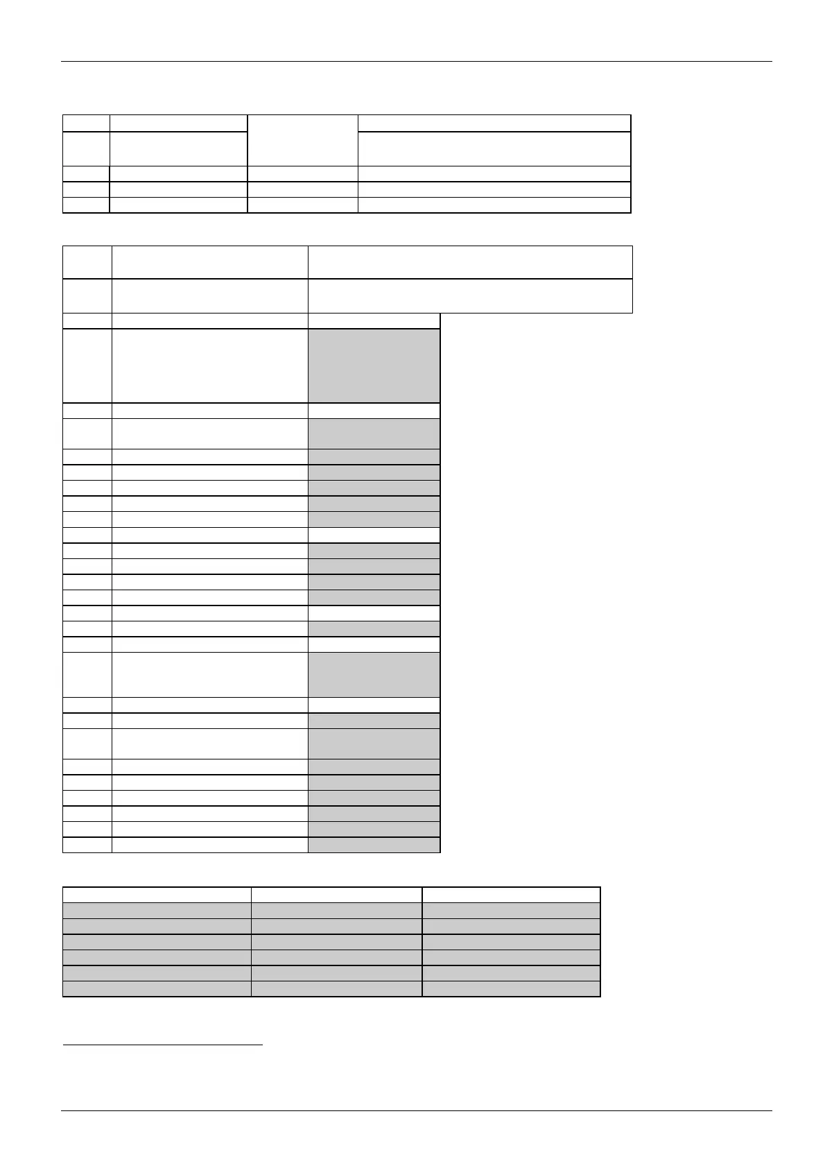
T-Nr. Designation Message
1:x Additional
functions
address
x =
111 Additional functions 1 812, 1, 0, ...
43)
Read and write (on = 1/off = 0);
112 Additional functions 2 820 ,1, 0, ...
41)
write depending on version of release unit
T-Nr. Designation Increments for parameterizable functions
(highlighted in grey)
1:x Setting values/
Protection parameters
All releases
x =
61 "a" release setting current I
r
Ampere values in
accordance with
Table 4
Example: In accordance with
Table 4, increment for T-Nr. 1:61
for I
n
= 630 A is:1 from 252 A to
500 A and 5 from 501 A to 630 A
64 Time-lag class T
c
(trip class) Increment = 1
(20, 21, ...)
65 "z" release setting current I
d
As for T-Nr. 1:61
66 "z" release delay t
d
Increment = 1
71 "g" release setting current I
g
As for T-Nr. 1:61
72 "g" release delay t
g
Increment = 1
81 "N" release setting current I
N
As for T-Nr. 1:61
82 "n" release setting current I
i
As for T-Nr. 1:61
83 "g/N" release type I
g
/N Increment = 1
84 I
n, ext
External current transformer In acc. with Table 4
85 Release time or alarm t
x
Increment = 1
93 Current phase imbalance Increment = 1
(For N and P with
Z=F05 only)
101 Voltage phase imbalance Increment = 1
102 Reversal of direction of power
flow
(See footnote
44
)
)
103 Overfrequency f> In acc. with Table 4
104 Underfrequency f< In acc. with Table 4
105 Overvoltage U> In acc. with Table 4
106 Undervoltage U< In acc. with Table 4
107 Load shedding (Output OFF) As for T-Nr. 1:61
108 Load input (Output ON) As for T-Nr. 1:61
3WN6 circuit-breaker - Overcurrent release increments for parameter settings:
from to Increment
>1 10 0.1
> 10 500 1
> 500 1000 5
> 1000 5000 10
> 5000 10000 50
> 10000 50000/65000 100
Table 4
43)
See pages 50 -51 for further details of exact addressing.
44)
The increment for the power flow direction parameterization value is 1 up to 500 kW. For 501 - 2000 kW, it is in accordance with Table 4

 Loading...