LOGO! Manual
A5E00067781 01
164
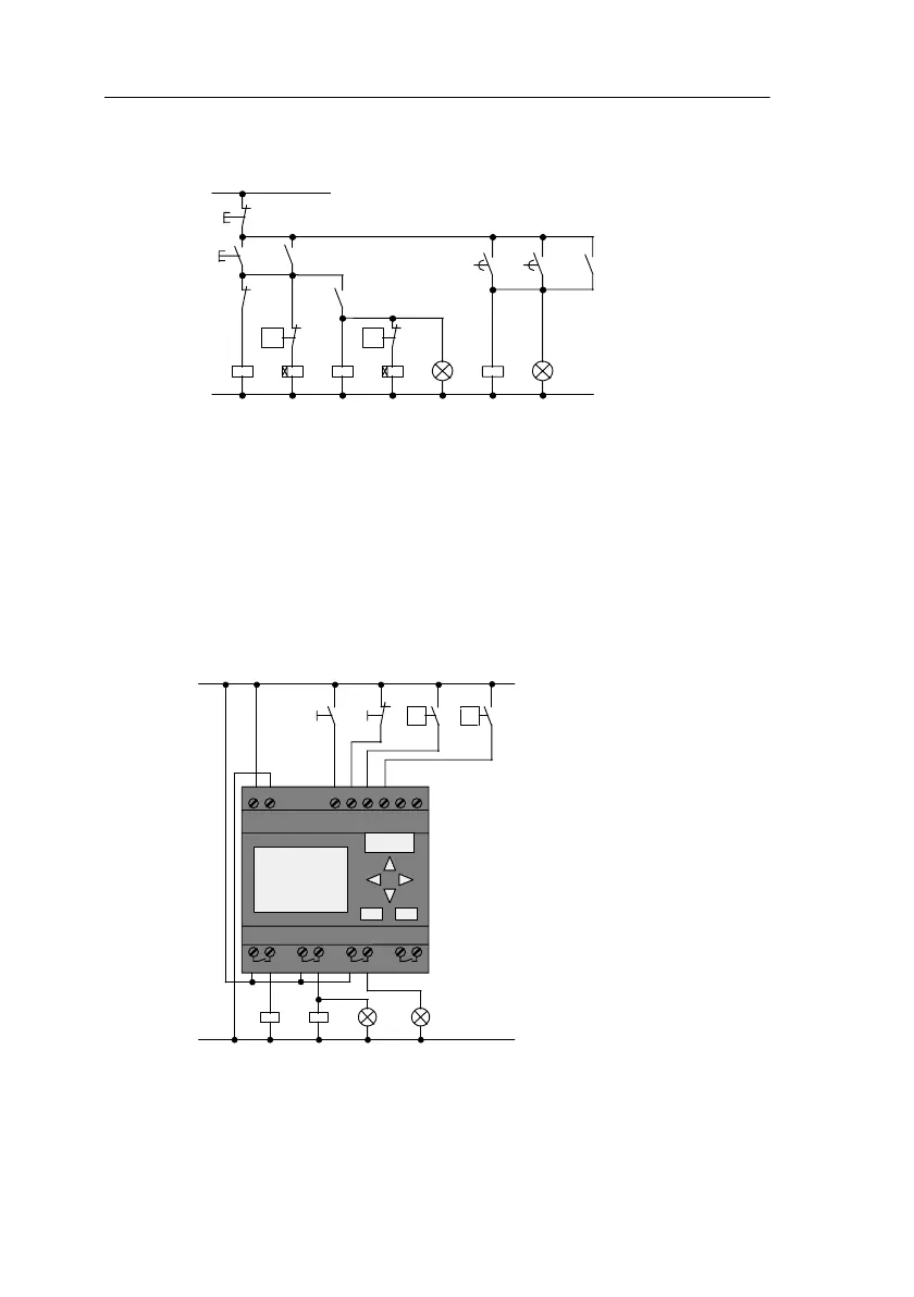
The circuit diagram for the previous solution is as follows:
K1 K5
K5
S1
Stale air Fresh air
S0
K3K2
Operation
Auxiliary circuit
L1
N
S2
K1
v
>
S2
H1
K4
S3
v
>
K5
Fault
H2
K2 K4
The fans are monitored by flow sensors. If, after a short
delay, no air flow is registered, the system is switched off
and a fault reported. Acknowledge this by pressing the stop
switch.
Monitoring the fans requires an analyzer circuit with several
switching devices in addition to the flow sensors. The ana-
lyzer circuit can be replaced by a single LOGO! module.
Wiring of the ventilation system with LOGO! 230RC
L1N I1I2I3I4I5I6
Q1 Q2 Q3 Q4
SIEMENS
K1 K2
Exhaust fan Fresh-air fan
S1
L1
N
S2 S3
v>
v>
H1 H2
S0
LOGO! 230RC
Applications
 Loading...