LOGO! Manual
A5E00067781 01
70
Logic table for OR:
123Q
0 0 0 0
0011
0101
0111
1001
1011
1101
1111
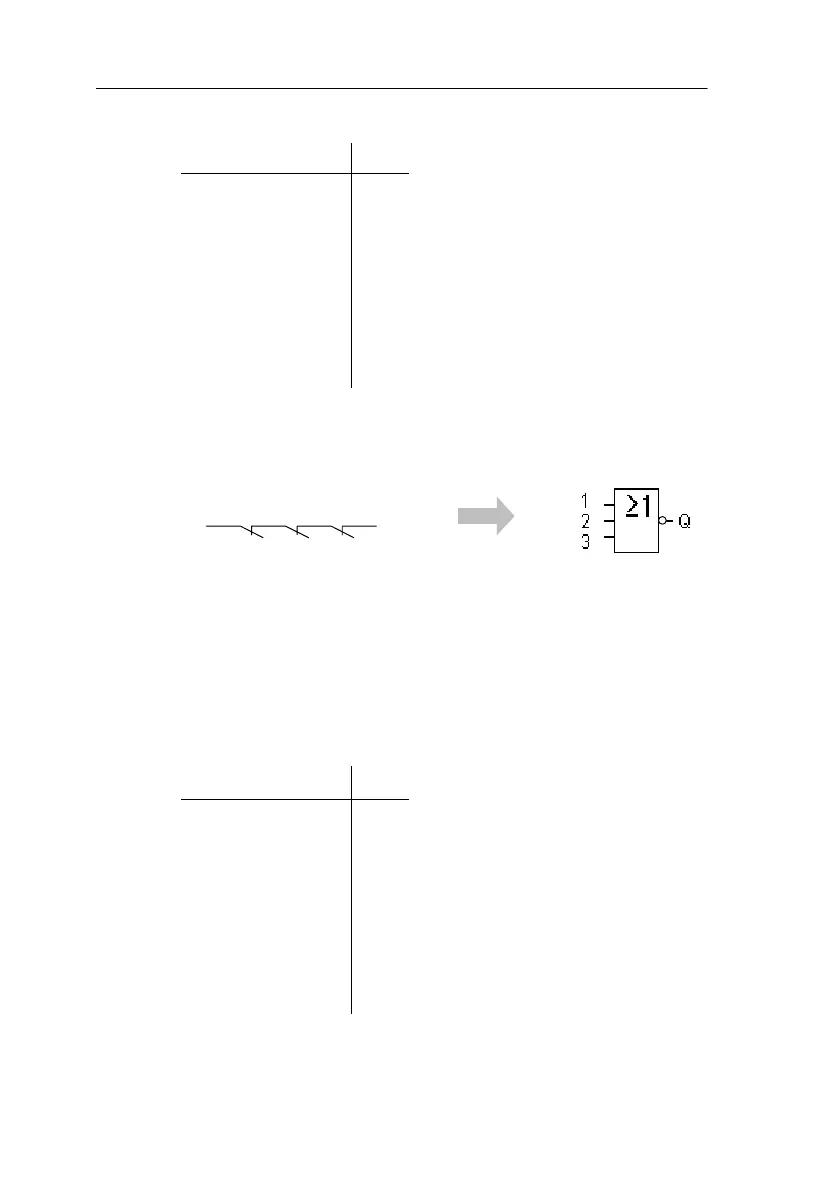
4.2.6 NOR (OR Not)
The series connection of a number of
normally closed contacts is represented
in a circuit diagram as follows:
Symbol in LOGO!:
The output of NOR only adopts the state 1 if all the inputs
have the state 0 (i.e. they are switched off). As soon as
any of the inputs is switched on (state 1), the output of
NOR is set to 0.
If an input pin of this block is not wired (x), then the follow-
ing applies to the input: x = 0.
Logic table for NOR
123Q
0 0 0 1
0010
0100
0110
1000
1010
1100
1110
LOGO! Functions
 Loading...