LOGO! Manual
A5E00067781 01
174
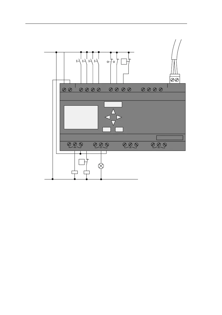
Wiring of the gate control system with LOGO! 230RCLB11
N
L1N I1I2I3I4
Q1 Q3 Q4
SIEMENS
I5 I6
Q2
Q5 Q6 Q7 Q8
Output 8x
I7
I8
AS interface
– +
I9 I10 I11 I12
K1
K2
L1
Gate
closed
Gate
open
Flashing
light
S0 S1 S2 S3 S4 S5
S6
p
>
S6
p
>
Components used
K1 Master contactor opening
K2 Master contactor closing
S0
(NO contact)
OPEN cord-operated switch
S1
(NO contact)
CLOSE cord-operated switch
S2
(NO contact)
Open switch
S3
(NO contact)
Close switch
S4
(NC contact)
OPEN GATE position switch
S5
(NC contact)
CLOSE GATE position switch
S6
(NC contact)
Safety pressure bar
Applications
 Loading...