LOGO! Manual
A5E00067781 01
34
You convert the circuit to blocks. To do this, go through the
circuit from the output to the input:
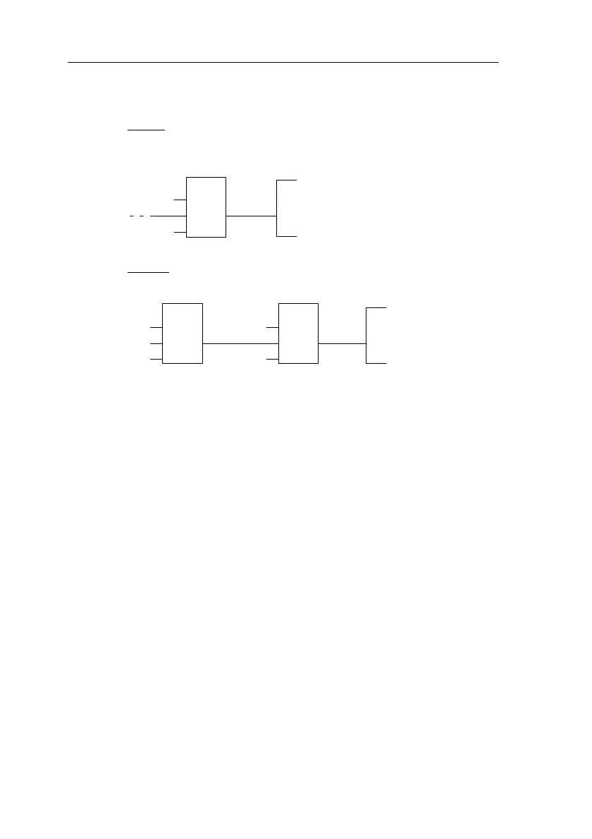
Step1: At output Q1 there is a series connection of the nor-
mally open contact S3 with another circuit component. The
series connection corresponds to an AND block:
I3
x
Q1
&
Step 2: S1 and S2 are connected in parallel. The parallel
connection corresponds to an OR block:
I3
x
Q1
&
1
I1
I2
x
You have now provided a complete description of the circuit
for LOGO!. You now need to connect the inputs and out-
puts to LOGO!.
Wiring
Connect switches S1 to S3 to the screw connectors of
LOGO!:
Connect S1 to connector I1 on LOGO!
Connect S2 to connector I2 on LOGO!
Connect S3 to connector I3 on LOGO!
Only 2 inputs of the OR block are used so the third input
must be marked as unused. This is indicated by the x next
to it.
Likewise, only 2 inputs of the AND block are used. The
third input is therefore also marked as ’unused’ by an x
next to it.
The output of the AND block controls the relay at output
Q1. Consumer E1 is connected at output Q1.
Pro
rammin
LOGO!
 Loading...