2-5
Primer: S7-300 Programmable Controller, Quick Start
C79000-G7076-C500-01
In order for the TLIGHT sample program to simulate a traffic light control
system on the simulator module of your S7-300, you must define the
following addresses to which you can also assign a symbolic name:
S 2 inputs (I) for requesting green for the pedestrians on both sides of the
street.
S 5 outputs (Q) for controlling the signal indicators of both sets of lights.
S 1 memory bit (M) for switching the signal after a green request from a
pedestrian.
S 5 timers (T) to determine the duration of each signal phase. The timers
each have the S5Time format.
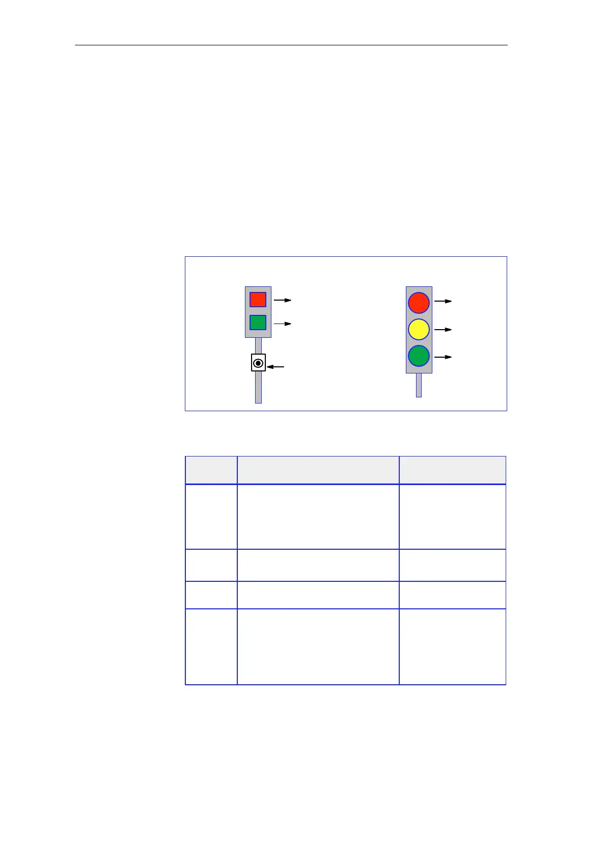
I 0.0 and I 0.1
Q 0.5
Q 0.6
Q 0.7
Pedestrian light
Vehicle light
Q 0.0
Q 0.1
Figure 2-4 Traffic Light Indicators and the Required Inputs and Outputs
Address Description
Example of Symbolic
Names
Q 0.0
Q 0.1
Q 0.5
Q 0.6
Q 0.7
Red for pedestrians
Green for pedestrians
Red for vehicles
Yellow for vehicles
Green for vehicles
Ped_Red
Ped_Green
Veh_Red
Veh_Yel
Veh_Green
I 0.0
I 0.1
Pushbutton on right-hand side of street
Pushbutton on left-hand side of street
Pushb_Right
Pushb_Left
M 0.0 Memory bit for switching the signal
after a green request from a pedestrian
Signal_Mem
T 2
T 3
T 4
T 5
T 6
Duration of yellow phase for vehicles
Duration of green phase for pedestrians
Delay red phase for vehicles
Duration of red/yellow phase for
vehicles
Delay next green request for pedestrians
Veh_Yel_Phase
Ped_Green_Phase
Veh_Del_Red
Veh_Red_Yel_Phase
Ped_Del_Green
Which Addresses
Do You Need?
Defining and Structuring the Control Task
 Loading...


