Operator Control 09.02
6-2 Siemens AG 6SE7087-6AK85-1AA0
Rectifier/Regenerating Unit Operating Instructions
6.2 Displays
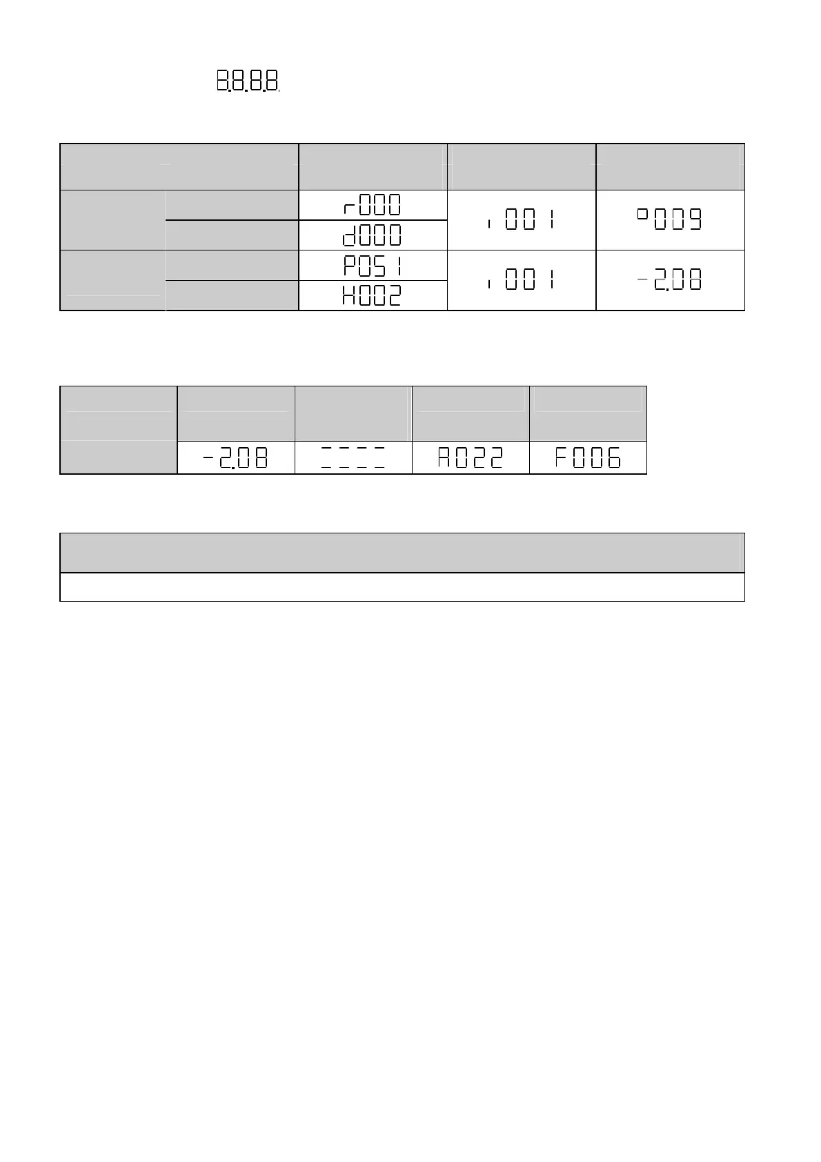
Tables 6.2 and 6.3 below give an overview of the displays that can be shown on the PMU:
Parameter number Index Parameter value
e.g. e.g. e.g.
Basic converter
Visualization
parameters
Technology board
Basic converter
Setting
parameters
Technology board
Table 6.2 Displaying visualization and setting parameters on the PMU
Actual value
Parameter value
not (yet)
possible
Alarm
Fault
Display
Table 6.3 Status display on the PMU
NOTE
The parameters are described in Chapter 5 and the fault and alarm messages are described in Chapter 7.
Once the electronics supply voltage has been switched on, either the PMU operating display shows the current
operating state of the rectifier/regenerating unit (e.g. o009) or a fault or alarm message is displayed (e.g. F060).
The operating states are described in Section 5.1 and the fault and alarm messages are described in Sections
7.1 and 7.2.
As described in Section 6.3 (Figures 6.2 and 6.3), it is possible to change over from one display level to
another.
By pressing <P>, it is possible to change from the status display (e.g. o009) to the parameter number level in
which the separate parameters can be selected via <raise> or <lower>. The selected access level (P051) and
the operating state (r000, r001) determine here which parameters are displayed. All parameters are not always
visible (see Chapter 5/overview of the abbreviations/footnotes 5 to 8)!
Pressing <P> again switches to the index level for indexed parameters (see Section 4.1.2) but directly to the
parameter value level for all other parameters and the index or the value can be modified via <raise> and
<lower>. The same conditions apply for changing a parameter value as were described for the parameter
number, i.e. a parameter value can only be modified under an appropriate access level and an appropriate
operating state.
If the 4 characters of the seven-segment display are insufficient for displaying a parameter value, only 4 figures
will be displayed initially (see Figure 6.4). The presence of further figures to the right or left of this "window" is
indicated by flashing of the left-hand or right-hand figure. If <P>+<lower> or <P>+<raise> are pressed
simultaneously, this "window" can be moved to view the parameter value.
By pressing <P> again, it is possible to switch back to the parameter number level..
AoteWell Automation Sales Team
Buy Siemens PLC HMI Drives at AoteWell.com
 Loading...