s
________________________________________________________________________________
Siemens Energy & Automation, Inc. 3333 Old Milton Parkway Alpharetta, GA 30202
11
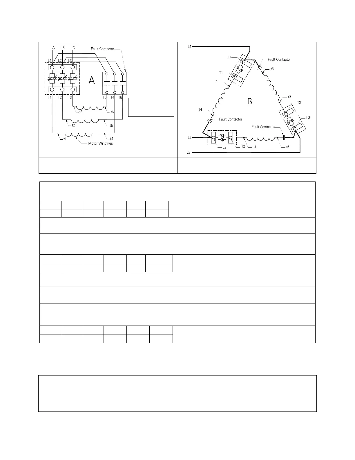
Figure 4: Connection Diagram
Figure 4a: Motor Wiring for In Delta
Applications
Single Voltage Motors
6 lead motor (208 – 575VAC)
T1 T2 T3 T6 T4 T5
1 2 3 6 4 5
Soft Starter
Motor Leads
Dual Voltage Motors
High Voltage Connections, 12 lead motor, (460-480 VAC)
T1 T2 T3 T6 T4 T5
1 2 2 12 10 11
Soft Starter
Motor Leads
Motor Leads tied together in the motor: 4&7 5&8 6&9
Low Voltage Connections, 12 lead motor, (220-240 VAC)-
T1 T2 T3 T6 T4 T5
1,7 2,8 3,9 6,12 10,4 11,5
Soft Starter
Motor Leads
Note:
This Solid State starter is wired at the factory for in-delta operation on 6 and 12 lead motors only! If you
have a 9 lead delta motor, you must run it as the “In Line” configuration show on the following page. If you have a
submersible application where only 3 motor leads are brought to the starter, you may elect to run the starter “in line”
also. When running “in line”, the correct size starter must be used. The following pages show how to connect the
starter in the “In Line” configuration.
Note the arrangement
of motor terminations
T6, T4, and T5

 Loading...


