s
________________________________________________________________________________
Siemens Energy & Automation, Inc. 3333 Old Milton Parkway Alpharetta, GA 30202
7
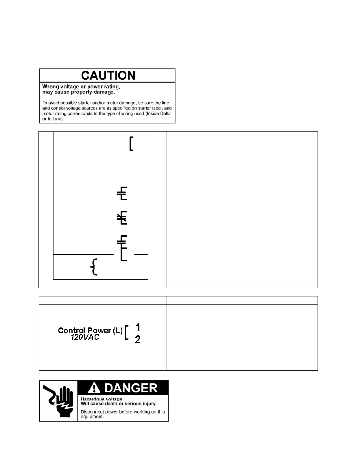
Control Power Connections:
Terminal Customer Connections
A 120 VAC, 500VA supply should be connected
between the Line and Neutral terminals, points 1
and 3. This supply also powers the fault contactor.
Terminals 1 and 2 are internally connected. An
external jumper wire is required to connect
terminal 1 to terminal 9 to feed the NO Ready
contacts.
Figure 2: Control Power Connections
The customer control connections on the Solid
State Elevator Starter feature a removable terminal
block. The layout is shown to the left. All
terminations are screw type.
To
Contactor
Terminals 1 and 2 are tied internally in unit
Terminals 3 and 12 are tied internally in unit
10
Coil
Coil (N)
12
11
3
Control Power (N)
NC Ready
Up to Speed
Run Input
NO Ready
7
8
9
5
6
4
120VAC
Control Power (L)
1
2

 Loading...


