s
________________________________________________________________________________
Siemens Energy & Automation, Inc. 3333 Old Milton Parkway Alpharetta, GA 30202
8
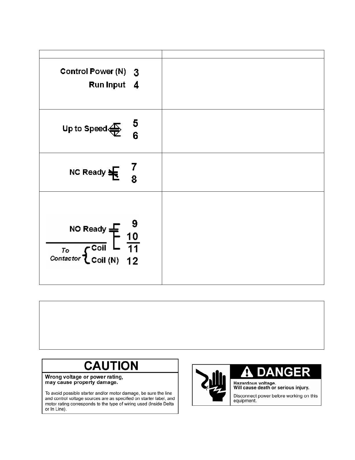
Terminal Customer Connections
The 120 VAC motor run signal is connected to terminal
4. The neutral of the motor run circuit must be
referenced to terminal 3, the neutral of the Control
Power input.
This output is used to either directly supply power to
the Up valves or supply a signal to a control board to
indicate the motor is up to speed. This output utilizes a
Triac rated for 120 VAC.
This contact may be used to signal a control board that
the unit is in a fault condition.
Terminal 9 should be connected via a jumper wire to
either terminal 1 or 2. This provides a hot feed to the
fault contactor coil when the NO Ready contact is
closed.
The terminals marked 10 and 11 are the switched side
of the NO Ready contact. This configuration allows
terminal 10 to be used to signal that the starter is ready
to run while terminals 11 and 12 (neutral for the fault
contactor coil) control the fault contactor.
Figure 2a: Control Power Connections
Note:
---Terminals 1 and 2 are tied together inside the unit as are terminals 3 and 12.
---The load on terminals 5 and 6 must not be greater than 1 amp at 120V. The load on
terminals 7 - 11 must not be greater than 3 amps at 120V. All terminals are rated for AC
voltages only.

 Loading...


