14 Mechanical installation and wiring
ARCADIS Varic/Orbic SPR2-310.812.03.01.02 Siemens AG
09.06 CS PS SP
Page 14 of 20
Medical Solutions
Wiring the Y cable
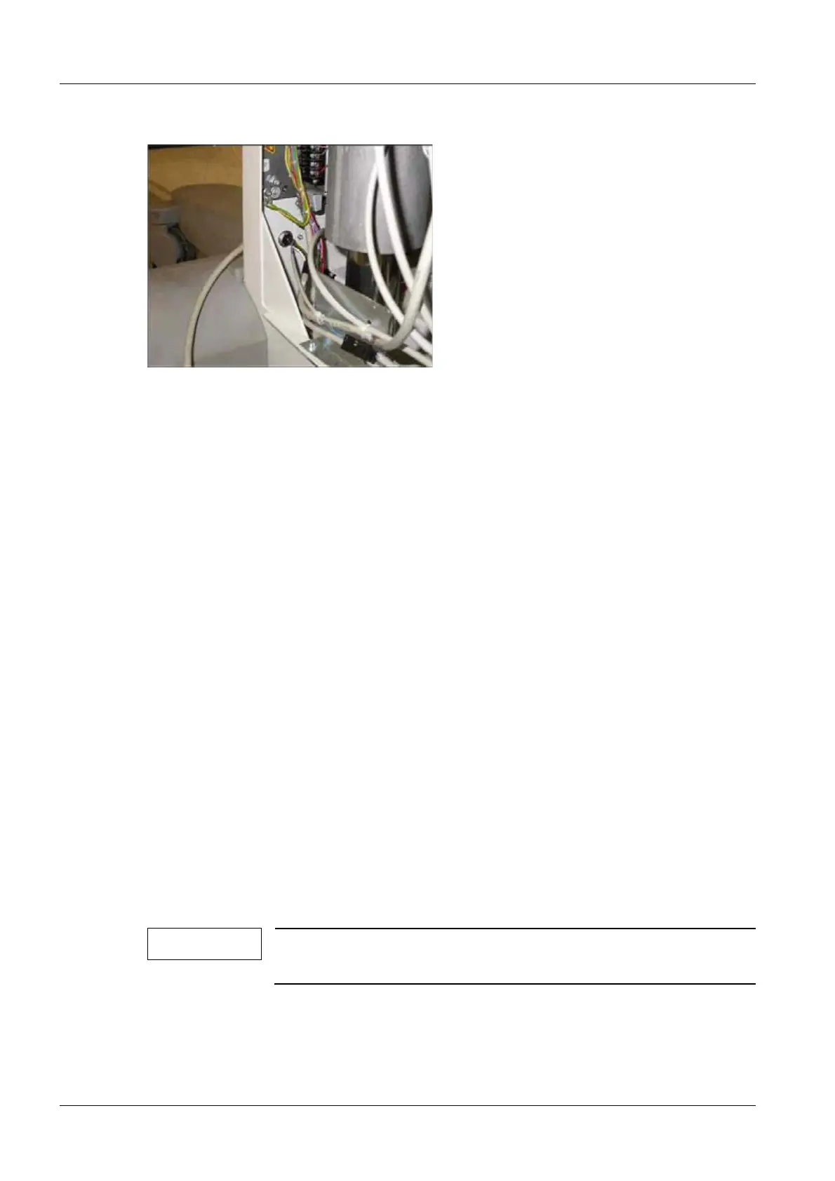
Fig. 10: X21 plug location
• Wire the Y cable from the accessory kit as follows:
¹ Plug the Y cable's D31.X2 plug into the new D31.X2 board.
¹ Plug the Y cable's D31.X5 plug into the new D31.X5 board.
¹ Plug the Y cable's RNH.3 plug into the M16.K1.3 relay.
¹ Plug the Y cable's RNH.4 plug into the M16.K1.4 relay.
¹ Plug the Y cable's D1.X14 plug into the D1.X14 board.
¹ Plug the Y cable's X21 plug into the open X21 socket, connected to the foot-
switch mounting jack. See (Fig. 10 / p. 14).
• Attach the ends of the Y cable along the existing cable assemblies using the cable ties
included in the accessory kit.
• Insert the plug for the multi-function footswitch into the footswitch socket and lock it in
place.
Wiring for systems with the 3D reconstruction option installed 0
Wiring the Y cable
• Modify the Y cable from the accessory kit as follows:
¹ Locate the wires labeled RNH.3 and RNH.4. These lead to the Y cable's D1.X14
plug.
¹ Cut the RNH.3 and RNH.4 wires at a distance of about 8cm from the D1.X14 plug,
and insulate them with heat-shrink tubing. The label with the designation D1 X14
should still be in place and should remain so.
NOTE
The RNH.3 and RNH.4 wires are not needed when the 3D recon-
struction option is installed.

 Loading...