Installing
3.3 Terminal strips on CU240B-2 Control Units
CU240B-2 and CU240E-2 Control Units
10 Compact Operating Instructions, 04/2015, A5E35792002B AA
Terminal strips on CU240B-2 Control Units
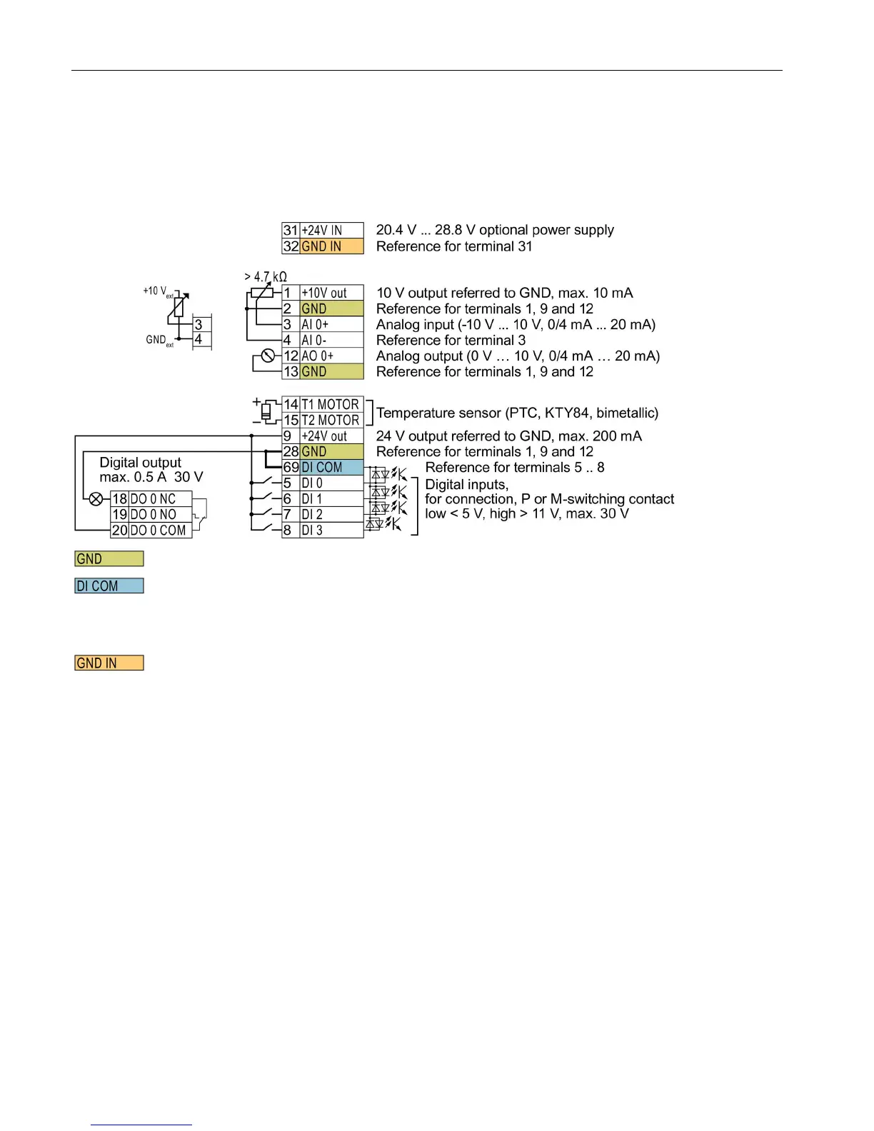
Terminal strips with wiring example
All terminals labelled with reference potential "GND" are connected internally in the inverter.
Reference potential "DI COM" is electrically isolated from "GND".
→ If, as shown above, the 24 V supply from terminal 9 is used to supply the digital inputs, then you
must connect "GND" to "DI COM".
Terminals 31, 32
Reference potential "GND IN" is electrically isolated from "GND". When an optional 24 V power supply
is connected at terminals 31, 32, even when the Power Module is disconnected from the line supply,
the Control Unit remains in operation. The Control Unit thus maintains the fieldbus communication, for
example.
→ at terminals 31, 32, only connect a power supply that is in accordance with SELV (Safety Extra Low
Voltage) or PELV (Protective Extra Low Voltage).
→ if you use a common external power supply for terminals 31, 32 and the digital inputs, you must
connect "GND" to "GND IN".
Terminals 3, 4: You may use the internal 10V power supply or an external power supply for the analog input.
→ If you use the internal 10 V power supply, you must connect AI 0- to GND.
Figure 3-1 Wiring example of the digital inputs with the internal inverter 24 V power supply

 Loading...


