GAMMA instabus
Technical Product Information
March 2008
DELTA profil Display and control unit UP 585 5WG1 585-2AB_1
DELTA style Display and control unit UP 584 5WG1 584-2AB_1
DELTA ambiente Display and control unit UP 586 5WG1 586-2AB_1
Siemens AG UP 58x, 6 pages Technical Manual
Automation and Drives Group
Electrical Installation Technology © Siemens AG 2008 Update: http://www.siemens.com/gamma
P.O. Box 10 09 53, D-93009 Regensburg Subject to change without prior notice
2.3.1.2/3
Electrical safety
• Degree of pollution (according to IEC 60664-1): 2
• Type of protection (according to EN 60529): IP 20
• Protection class (according to IEC 61140): III
• Overvoltage category (according to IEC 60664-1): III
• Bus: safety extra-low voltage SELV DC 24 V
• Device complies with EN 50090-2-2 and IEC 60664-1
EMC requirements
• complies with EN 50081-1, EN 50090-2-2 and
EN 61000-6-2
Environmental conditions
• Climatic withstand capability: EN 50090-2-2
• Ambient operating temperature: - 5 ... + 45 °C
• Storage temperature: - 25 ... + 70 °C
• Relative humidity [not condensing): 5 % to 93 %
Reliability
• Rate of failure: 572 fit
Markings
• KNX EIB
CE mark
• In accordance with the EMC guideline (residential and
functional buildings) and the low voltage guideline
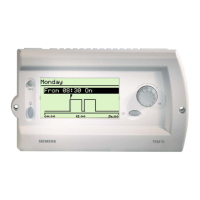
Location and function of the operating ele-
ments
Diagram 2: Location of the display and operating ele-
ments
A1 LC display (LCD) for indicating the messages
A2 Push buttons for scrolling through the lines
(UP / DOWN)
A3 Push buttons for controlling the selectable bus
functions
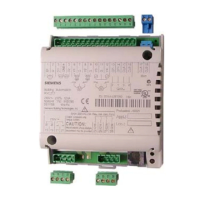
Installation of the driver
General description
The display unit is placed on the driver together with
the relevant frame.
The driver with bus connection is inserted in boxes of
60 mm ∅ using screw fixing.
The connection to the bus line is carried out via plug-in
screwless terminals for single-core conductors.
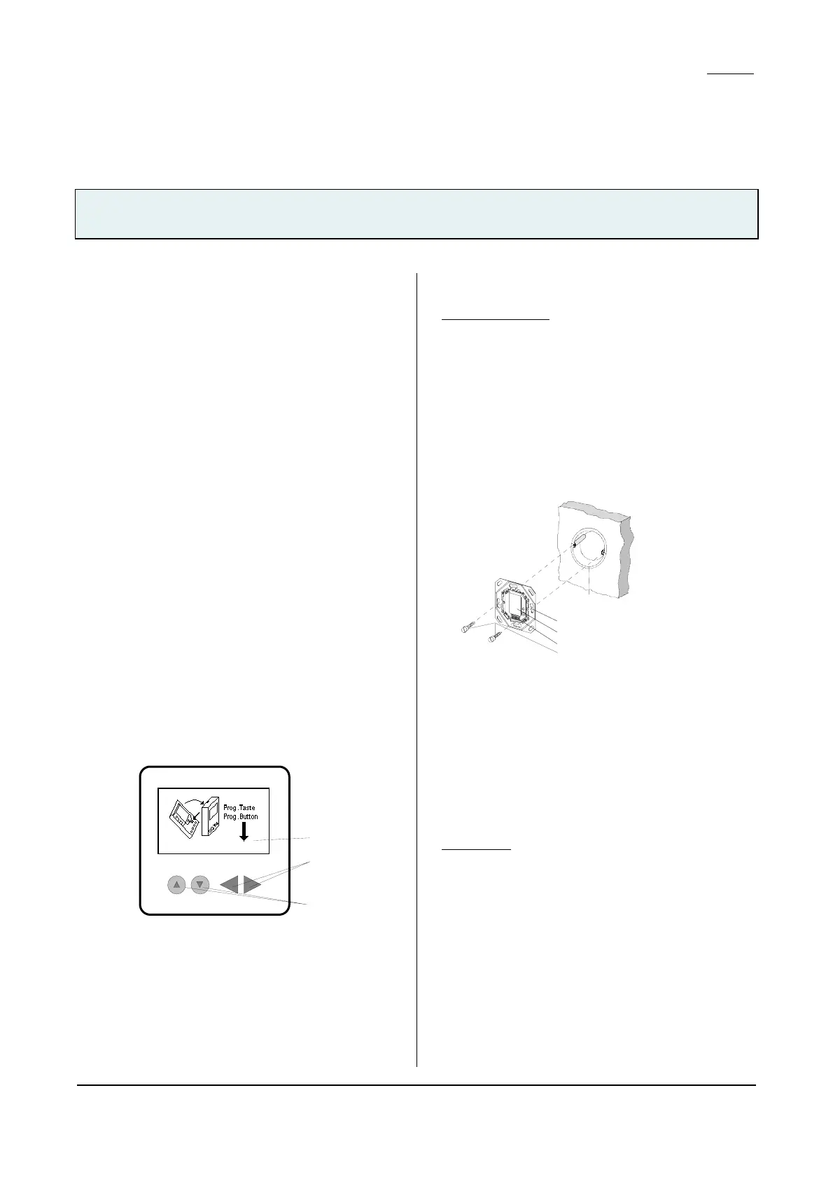
The driver with bus connection should be mounted so
that the interface is located at the bottom (Diagram 3).
This ensures that the display unit that is connected to
the interface is mounted in the correct operational posi-
tion.
C5
C4
C3
C2
C1
Diagram 3: Installation of the driver with bus
connection
C1 Installation box (60 mm Ø according to
DIN 49073)
C2 Slots for fixing
C3 Driver with bus connection
C4 Interface
C5 Fixing screws
Bus terminal
(Diagram 4)
The bus terminal (D2) is located at the rear of the driver.
1
3
2

 Loading...