GAMMA instabus
Technical Product Information
March 2008
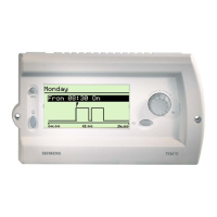
DELTA profil Display and control unit UP 585 5WG1 585-2AB_1
DELTA style Display and control unit UP 584 5WG1 584-2AB_1
DELTA ambiente Display and control unit UP 586 5WG1 586-2AB_1
Technical Manual UP 58x, 6 pages Siemens AG
Automation and Drives Group
Update: http://www.siemens.com/gamma © Siemens AG 2008 Electrical Installation Technology
Subject to change without prior notice P.O. Box 10 09 53, D-93009 Regensburg
2.3.1.2/4
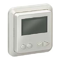
Connecting the bus cable
(Diagram 4)
− The bus terminal (D2) is suitable for single-core con-
ductors with 0.6 ... 0.8 mm Ø.
− The bus terminal (terminal block) (D2) consists of two
components (D2.1, D2.2), each with four terminal
contacts, Diagram 7.
− Strip the insulation from the conductor (D3) and place
in the terminal (D2) (red = +, grey = -).
Diagram 4: Connecting the bus cable
Installation of the display
B1
B2
B3
B4
B5
B6
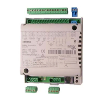
B1 Driver with bus connection
B2 Frames
B3 Intermediate frame (only for DELTA style)
B4 Display unit
B5 Screws for fixing the display unit onto the
driver B1
B6 Cover
- Place the display unit (B4) with B6 and the relevant
frame (B2) onto the driver (B1).
- Remove the cover (B6) from the display unit as de-
scribed under ‘Dismantling’ in order to program the
physical address.
- Secure the display unit (B4) with the two screws (B5).
- Now program the physical address.
The location of the programming button and the pro-
gramming LED is indicated in Diagram 5.
- Remove the protective film from the LC display,
Diagram 6c.
- Place the cover (B6) on the display unit again (B4).
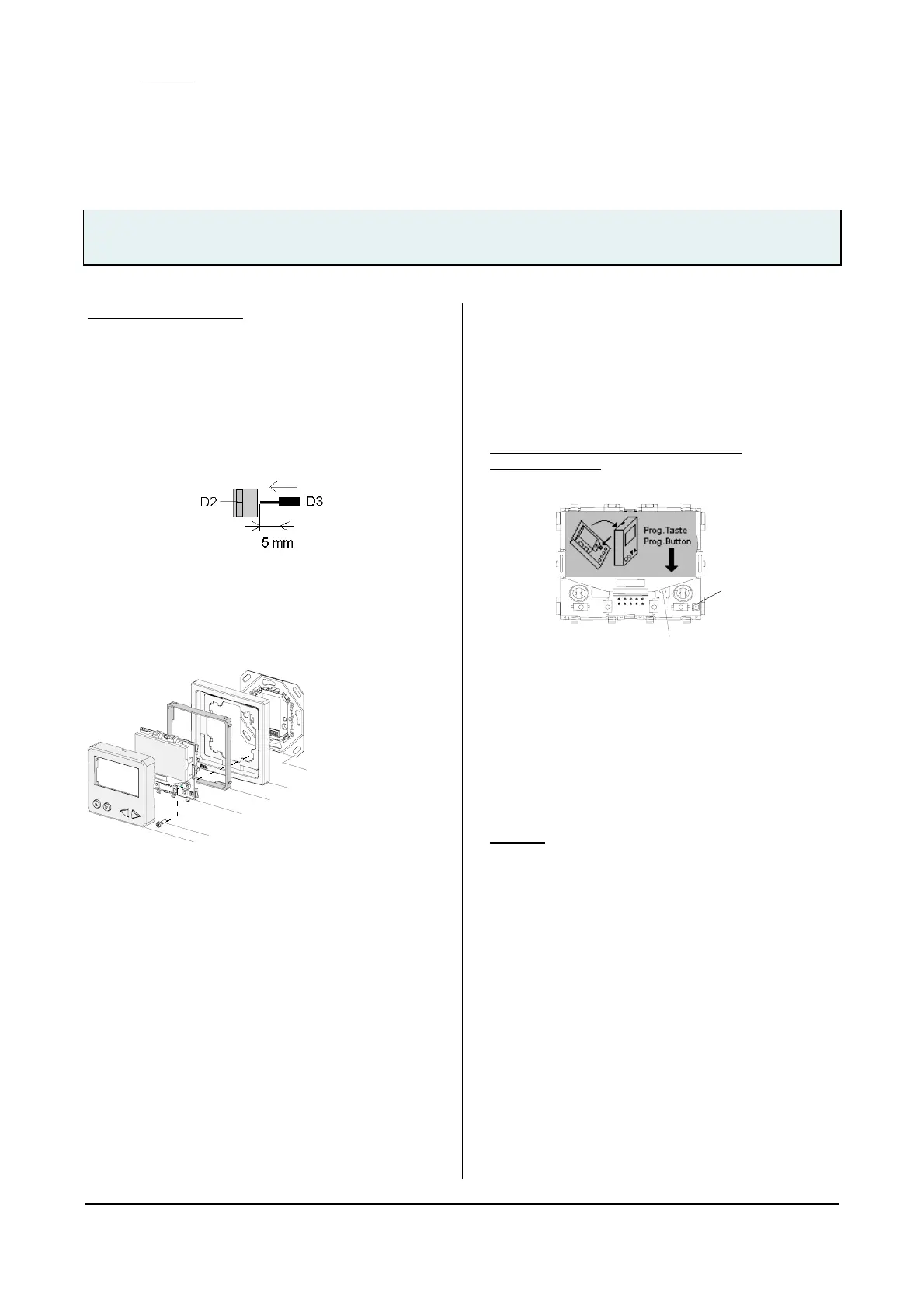
Location of the programming button and
programming LED
Diagram 5: Location of the programming button and LED
is also indicated on a non-configured LCD if
bus voltage has been applied
Dismantling
- Remove the cover as described in Diagram 6a or 6b.
Caution:
Do not touch any components apart from the program-
ming button (Diagram 6) as damage could otherwise be
caused.
- Loosen the fixing screws (B5).
- Place the cover (B6) back on the display unit (B4).
- Remove the frame (B2) together with the display unit
from the driver.
- Loosen the screws of the driver in the flush-type box
(Diagram 3).
- Separate the bus driver module from the bus cable
(Diagram 7).
Program-
ming LED
Programming-
button
 Loading...