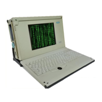
DEVICE PROGRAMMING UNIT USER’S MANUAL | CHAPTER 2
10 PROGRAMMING
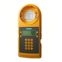
To Program/Test A Compatible FDUL Series Detector:
• Align the knobs to base portion of the DPU and insert
detector into base.
• Rotate the detector clockwise until it stops and locks in
place.
• To program the FDOT421/OH921, select the FC20
mode. The minimum revision to program the
FDOT421/OH921 is DPU revision 9.00.0009 or higher.
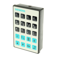
DPU
BASE
PORTION
OF DPU
LED
SYMBOL
LED
8
9
0
C
2
3
4
5
6
7
1
SERIES 11
DETECTOR
OR
FD-UL SERIES
DETECTOR
To Program/Test A Compatible Series 11 Detector:
To Remove Detector Head:
• Align LED in detector with LED symbol on base portion
of the DPU and insert detector into base.
• Rotate the detector clockwise until it stops and locks in
place.
• Rotate the detector counterclockwise until stop is
reached.
• Pull detector out of base.
Figure 2
Connecting The Device Programming Unit To Detectors And Devices
CABLE
P/N 555-133891
BOTTOM
OF DPU
HMS MANUAL
STATION
To Program/Test HMS/MSI, HTRI/TRI, HCP/ICP/ICP-B6,
FDCIO422, HZM/CZM-1/CZM-1B6 Devices:And ILED
• Insert the programming plug in one end of cable
P/N 555-133891 into the red and black banana
jacks in the cable compartment in the bottom of
the DPU.
• Insert the programming plug in the other end of
cable P/N 555-133891 into the programming
points of the device to be programmed.
*NOTE:
When programming or testing MXL
and FS-100 devices, the prong on
the same side of the programming
plug as the locating tab goes into
the black banana jack.
*
LOCATING
TAB
PROGRAMMING
PLUG
BLACK
BANANA
JACK