EasyManuals Logo

Siemens FDM1101-R Series User Manual

Siemens FDM1101-R Series
32 pages
To Next Page IconTo Next Page
To Previous Page IconTo Previous Page
Page #16 background imageLoading...
Page #16 background image
Structure and function
Setup
3
16 | 32
Building
Technologies
A6V10201150_d_en_
--
Fire Safety
2018
-
-
19
3.2 Setup
3.2.1 Connections
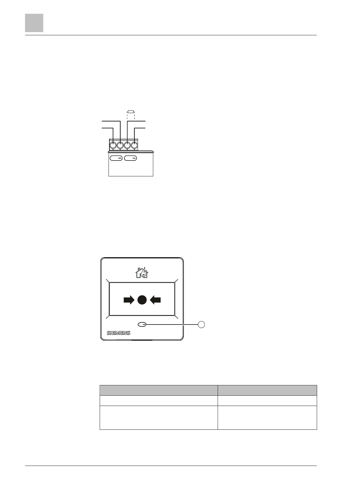
The back of the manual call points FDM1101-Rx is fitted with 4 terminals for the
detector line. At the end of the collective detector line, a control-panel-specific end-
of-line element (EOL) must be connected to the terminals.
Figure 4: Connection diagram for FDM1101-Rx
EOL Line termination element (End Of Line)
3.2.2 Indication elements
The manual call points FDM1101-Rx have a red LED. Only the optical fiber can be
seen from the outside.
Figure 5: LED in manual call point FDM1101-Rx
1 Red LED for 'Alarm'
LED red Meaning
Off Normal operation
Flashes light in intervals of 1 s, or is
permanently on (depending on the control
panel)
'Alarm'
LINE
LINE
EOL
+ +
FDM1101-Rx
1

Other manuals for Siemens FDM1101-R Series

Questions and Answers:

Question and Answer IconNeed help?

Do you have a question about the Siemens FDM1101-R Series and is the answer not in the manual?

Siemens FDM1101-R Series Specifications

General IconGeneral
BrandSiemens
ModelFDM1101-R Series
CategoryIndustrial Equipment
LanguageEnglish

Related product manuals