3 Views
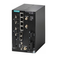
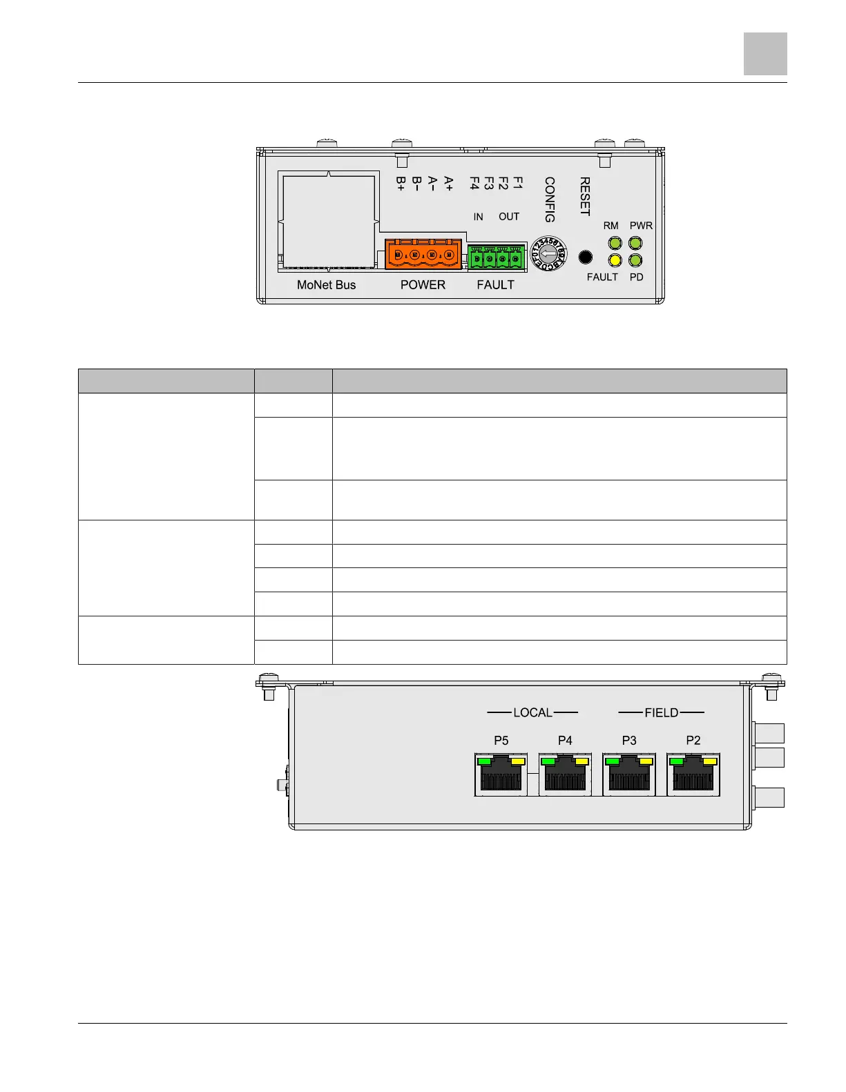
Figure 4: View of controls and indicators FN2012
Key for the operation and indication elements
Element Des. Function
Connector POWER X301 plug connection for external supply in the same housing or room
FAULT X302 connector strip for fault signals:
● F1/F2, dry contact relay for fault output
● F3/F4, not connected
MoNetBus Knock-out sheet cover on the X201 connector strip for the MoNet bus
flat cable
LEDs RM Redundancy manager indicator (redundancy master)
FAULT General fault
PWR Normal operation, hardware ready for operation
PD Not connected
Switches and keys CONFIG S302 rotary switch with 16 positions for pre-configured operating modes
RESET S301 RESET key with three functions
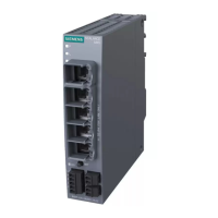
Figure 5: View of Ethernet connections FN2012
Views
3
A6V10407862_e_en_-- 11 | 32
 Loading...