7 Indicators
LED Color Function Condition Meaning
PWR Green Power LED Lit up ● Normal operation
Not lit up ● No power supply
FAUL
T
Yellow General fault See separate FAULT LED table
RM Green Redundancy manager See separate RM LED table
PD Green Not connected -- No function
-- No function
P2 Green/yellow Ethernet status LEDs Green ON ● Link up
P3 Green OFF ● Link down
P4 Yellow flashing ● Data communication active
P5 Yellow does not light
up
● No data communication
Table 1: Status LED
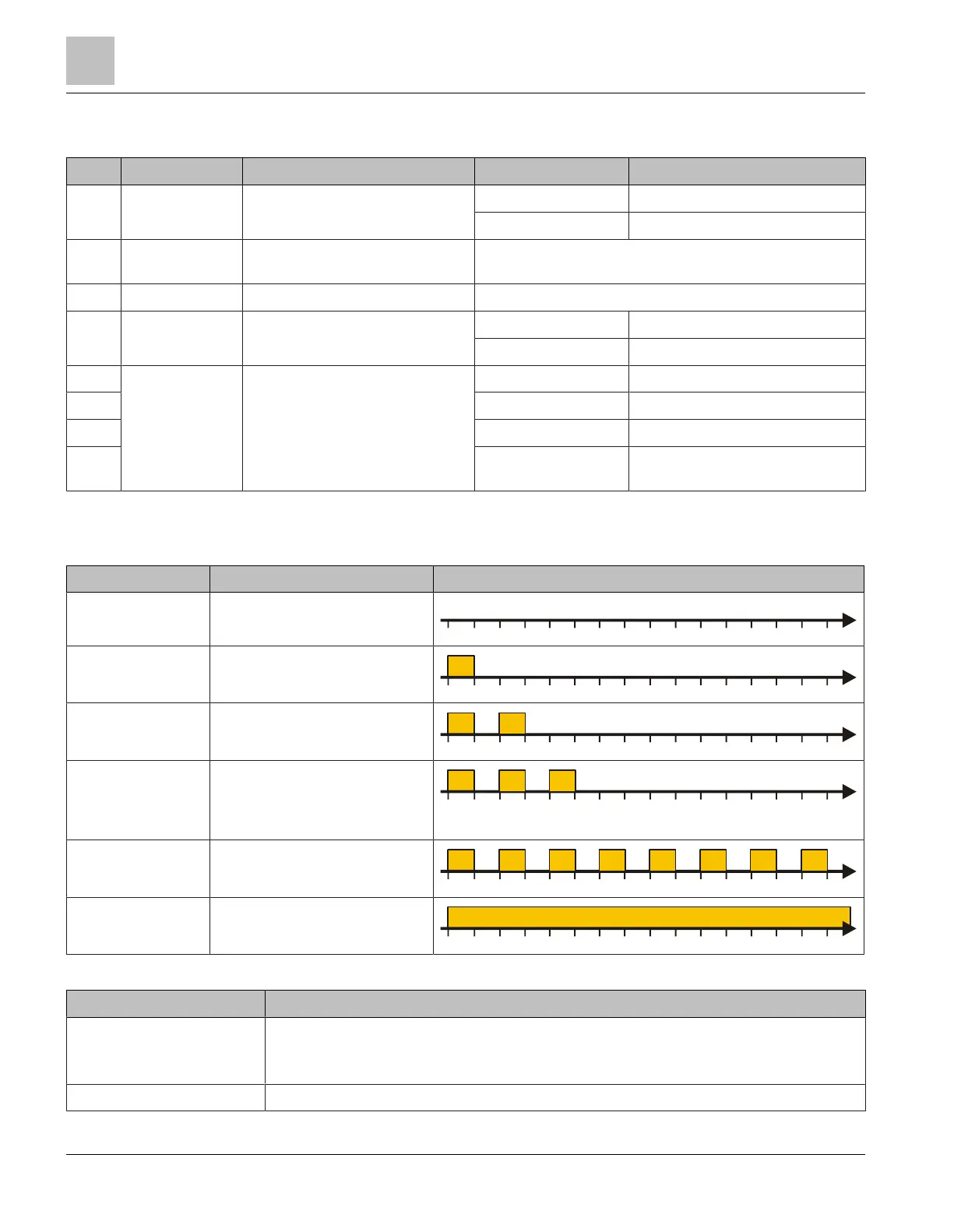
Function indicators for the FAULT LED
Function indicator Meaning FAULT LED flashing pattern (every 2s)
Normal Operation Normal operation
t
0 125 250 375 500 625 750 875 1000 1125 1250 15001375
[ms]
1625 1750 1875
FW Update Mode Ready for firmware update
t
0 125 250 375 500 625 750 875 1000 1125 1250 15001375
[ms]
1625 1750 1875
FW Update
Running
Ethernet switch is loading
firmware
t
0 125 250 375 500 625 750 875 1000 1125 1250 15001375
[ms]
1625 1750 1875
FW Update Failed FW update could not be
completed, network
connection may have been
interrupted
t
0 125 250 375 500 625 750 875 1000 1125 1250 15001375
[ms]
1625 1750 1875
Checksum Failed Incorrect firmware checksum
t
0 125 250 375 500 625 750 875 1000 1125 1250 15001375
[ms]
1625 1750 1875
Fatal FAULT Ethernet switch is generating
some other fault
t
0 125 250 375 500 625 750 875 1000 1125 1250 15001375
[ms]
1625 1750 1875
Table 2: FAULT LED flashing pattern
Function indicator Possible troubleshooting steps
FW Update Failed ● The Ethernet switch attempts to re-establish the connection in order to load the
FW.
● Restart the FW update via Desigo Fire Safety Works.
Checksum Failed ● Restart the FW update via Desigo Fire Safety Works.
Indicators
7
24 | 32 A6V10407862_e_en_--
 Loading...