6 Pin assignments
6.1 'POWER' connector strip
The 'POWER' connector is only needed if the supply is not possible via the MoNetBus
or PoE. This is generally only the case if the Ethernet switch (modular) is installed
remotely in another device. The power supply must be a DC24V power supply
featuring regulated and power-limited output that has been approved for fire alarm
signal applications.
Designation Description
A+ Supply input 1 (+DC24V)
A- Common supply input 1 (DC0V)
B- Not connected
B+ Not connected
Admissible cable cross-section: AWG24...AWG12/0.2...2.5 mm²
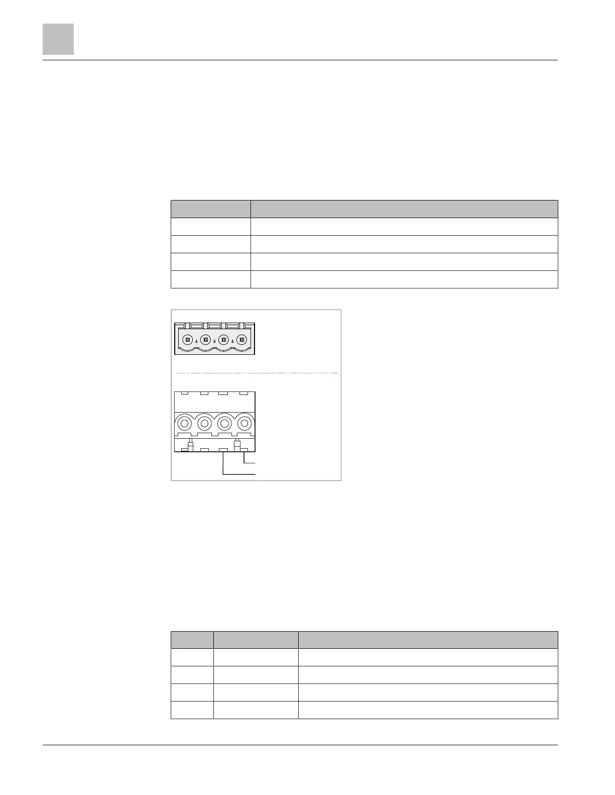
A+A-B-B+
POWER
+24V
GND
Terminal Plug
Connector FN2012
Supply input
6.2 'FAULT' connector strip
The fault output is a dry contact relay and, depending on the configuration, it can be
used to report fault states by means of contact interruption. When the FN2012 is
switched off, the relay contact is deactivated (opened).
The following fault messages can be configured via the web interface:
● 'Fatal fault': Ethernet switch(modular) malfunction
● 'Ring fault': Ring faults are only displayed if the Ethernet switch(modular) has the
function of the 'redundancy manager'
● 'Ring port fault': 'Link down' state of a ring port
Pin Designation Description
F1 OUT Dry contact relay 1 (common, normally open)
F2 OUT Dry contact relay 2 (common, normally open)
F3 IN Not connected
F4 IN Not connected
Pin assignments
'POWER' connector strip
6
22 | 32 A6V10407862_e_en_--
 Loading...