Function indicator Possible troubleshooting steps
Fatal FAULT ● Perform a reset. If that does not work, there is a hardware fault.
● Replace the Ethernet switch. Check whether any other fault messages are being
displayed in the FS20 system.
Table 3: Troubleshooting
Function indicators for the RM LED (redundancy manager)
Within each MRP
1
ring, there has to be a master Ethernet switch. All the other
Ethernet switches must perform the role of clients.
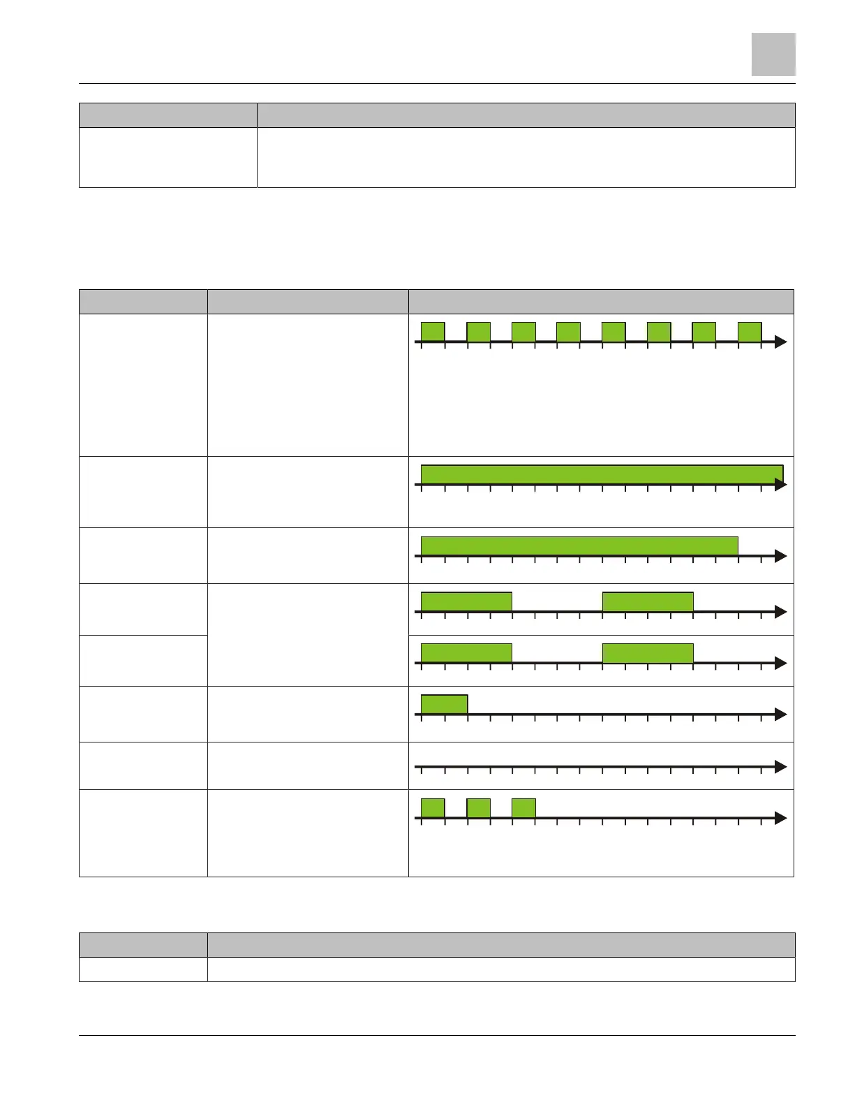
Function indicator Meaning RM LED flashing pattern (every 2s)
Search Manager Ethernet switch is being
initialized
System is looking for MRP
manager
Topology has changed
because Ethernet ring
participants have been added
or removed
t
0 125 250 375 500 625 750 875 1000 1125 1250 15001375
[ms]
1625 1750 1875
Manager Ethernet switch has been
configured as the manager
and is performing the ring
manager role
t
0 125 250 375 500 625 750 875 1000 1125 1250 15001375
[ms]
1625 1750 1875
Claim Manager Ethernet switch is acting as
the manager but has not been
configured to perform this role
t
0 125 250 375 500 625 750 875 1000 1125 1250 15001375
[ms]
1625 1750 1875
Manager
Ringopen
There is a break in the
Ethernet ring at one or more
locations
t
0 125 250 375 500 625 750 875 1000 1125 1250 15001375
[ms]
1625 1750 1875
ClaimManager
Ringopen
t
0 125 250 375 500 625 750 875 1000 1125 1250 15001375
[ms]
1625 1750 1875
Doublemanager Two Ethernet switches have
been configured as the
manager
t
0 125 250 375 500 625 750 875 1000 1125 1250 15001375
[ms]
1625 1750 1875
Client Ethernet switch has been
configured as a client
t
0 125 250 375 500 625 750 875 1000 1125 1250 15001375
[ms]
1625 1750 1875
Unidirectional Data
Link Fault
In one section of the MRP ring,
the connection is only running
in one direction due to
incorrect cabling or a hardware
fault
t
0 125 250 375 500 625 750 875 1000 1125 1250 15001375
[ms]
1625 1750 1875
Table 4: RM LED flashing pattern
1
MRP: Media redundancy protocol
Function indicator Possible troubleshooting steps
Claim Manager ● Adapt configuration. A ring manager has to be configured within each MRP ring.
Indicators
7
A6V10407862_e_en_-- 25 | 32
 Loading...