Transport, installation and assembly
3.10 Connection of the machine
A5E01083943A AB
Siemens AG Operating Instructions 2.02 1FW4
51
● the direction of rotation,
● the number and arrangement of the terminal boxes,
● the circuit and connection of the motor winding,
are specified in the section entitled "Technical data". The permissible direction of rotation
can also be seen on the motor rating plate.
Connection
Note
Ensure that there is a safe and reliable PE ground connection before starting any work.
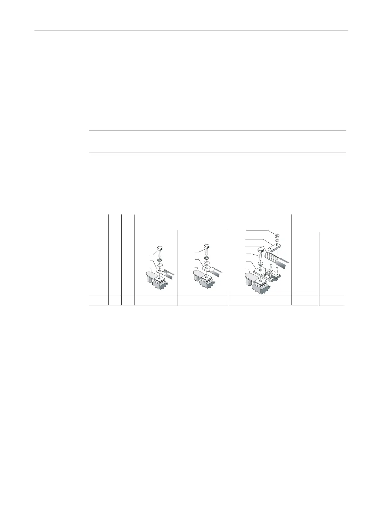
The connection must be made in such a way that a permanent, safe electrical connection is
maintained (no protruding wire ends). Use the matching cable end pieces. Depending on the
parts fitted, the connecting parts may be suitable for connection with or without cable lugs.
The available connection techniques, permissible conductor cross-sections, terminal sizes
and the associated tightening torques for the main terminals can be found in the following
representation.
5DWHGLQVXODWLRQYROWDJH
$GGLWLRQDOFRQYHUWHUSHDN
YROWDJH
1XWV
IRUOXJSDUW
7HUPLQDO
ER[W\SH
6XSSO\FDEOHFRQGXFWRUFURVVVHFWLRQWKDWFDQEHFRQQHFWHG
SRVVLEO\UHGXFHGE\WKHVL]HRIWKHFDEOHHQWU\
7KUHDGVL]HV
WLJKWHQLQJ
WRUTXHVIRUSDUW
QR
%ROWVIRU
PDLQ
WHUPLQDOV
3HDNYROWDJHSKDVHWRJURXQGDQGSKDVHWRSKDVH
RU
8PD[
;%
8LV
N9
N9
PP
PP PP
01P
01P
Figure 3-4 Connection of the power cable in the main terminal box
In some cases a terminal strip is installed in the main terminal box for the auxiliary circuit
connections. The connecting terminals of the auxiliary circuits are suitable for cable cross-
sections of up to 1.5 mm
2
(fine-wire) or 2.5 mm
2
(single-wire). The required insulation
stripping length on conductors for auxiliary terminals differs according to terminal type
(6 to 9 mm). When the length is correct, the conductor should reach the stop in the terminal
and at the same time the conductor insulation should reach the contact part of the terminal.