Transport, installation and assembly
3.10 Connection of the machine
A5E01083943A AB
52 Siemens AG Operating Instructions 2.02 1FW4
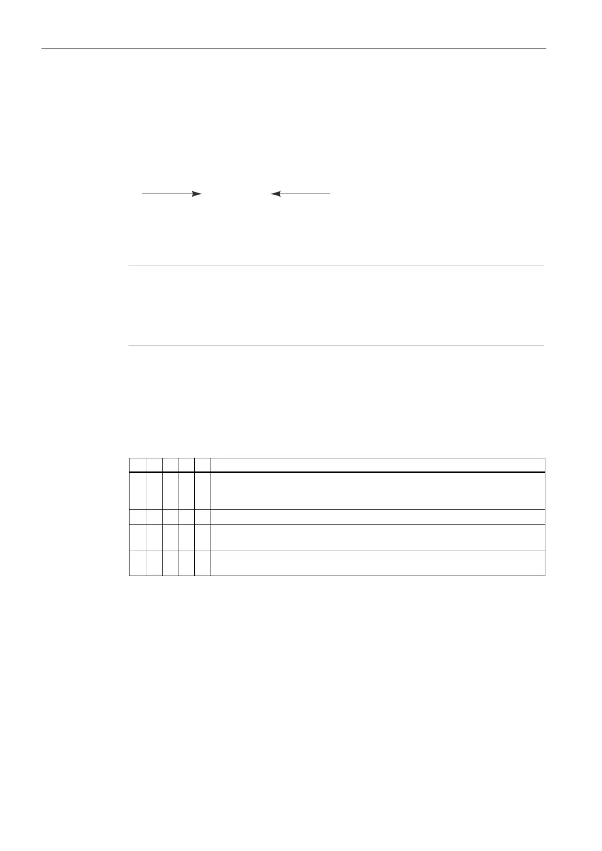
Direction of rotation
Connection of the power cables in the phase sequence L1, L2, L3 to U, V, W results in
clockwise rotation. If two of the connections are swapped then the resulting direction of
rotation is counter-clockwise (e.g. L1, L2, L3 to V, U, W). On motors which are only allowed
to run in one direction, the rating plate shows an arrow which indicates the permitted
direction of rotation, and it also specifies the terminal connections in the required phase
sequence.
&ORFNZLVH
&RXQWHUFORFNZLVH
89: 98:
Figure 3-5 Direction of rotation of the motor when looking at the drive end
Note
These restrictions in terms of the direction of rotation relate to the particular type of motor
design and result, for example, from the use of unidirectional fans. Any restrictions in terms
of the direction of rotation resulting from the installation itself are not shown in the
information on the rating plate and need to be considered separately when making the
connections.
Terminal designations
The following definitions apply in principle to the terminal designations of three-phase motors
in accordance with DIN VDE 0530 Part 8 or IEC 60034-8:
Table 3-4 Terminal designations (with the 1U1-1 as an example)
1 U 1 - 1 Identifier
x Index showing the pole assignment for pole-changing motors (where applicable,
a lower number indicates a lower speed) or, in special cases, for a subdivided
winding
x Phase designation (U, V, W)
x Index showing the start (1) / end (2) or tapping point of the winding (if there is
more than one connection per winding)
x Additional index for cases in which it is obligatory to connect parallel power feed
cables to several terminals with otherwise identical designations