Table of contents
A5E01083943A AB
6 Siemens AG Operating Instructions 2.02 1FW4
Figures
Figure 2-1
1FW4 water-cooled motor........................................................................................................... 24
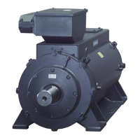
Figure 2-2 1FW4 air-cooled motor................................................................................................................ 24
Figure 2-3 Rating plate for water-cooled 1FW4 motors ............................................................................... 26
Figure 2-4 Rating plate for air-cooled 1FW4 motors .................................................................................... 27
Figure 2-5 Speed-torque characteristic for 1FW4 motors ............................................................................ 29
Figure 2-6 Example of a cooling circuit ........................................................................................................ 36
Figure 3-1 Aligning the motor ....................................................................................................................... 44
Figure 3-2 Cable with symmetrical cable cross-section ............................................................................... 47
Figure 3-3 Radio-frequency grounding......................................................................................................... 50
Figure 3-4 Connection of the power cable in the main terminal box ............................................................ 51
Figure 3-5 Direction of rotation of the motor when looking at the drive end................................................. 52
Figure 3-6 Strain relief device and sealing insert ......................................................................................... 54
Figure 6-1 Detailed view of the speed sensor for the water-cooled 1FW4 motor ........................................ 78
Figure 6-2 Replacing the sensor for the water-cooled 1FW4 motor ............................................................ 79
Figure 6-3 Detailed view of the speed sensor for the air-cooled 1FW4 motor............................................. 81
Figure 6-4 Replacing the sensor for the air-cooled 1FW4 motor ................................................................. 82
Figure 8-1 Stator and rotor ........................................................................................................................... 92
Figure 8-2 Stators and rotors, air-cooled version .........................................................................................93
Figure 8-3 Bearing bush DE ......................................................................................................................... 94
Figure 8-4 Bearing bush NDE ...................................................................................................................... 95
Figure 8-5 Mounted external fan .................................................................................................................. 96
Figure 8-6 Pulse encoder ............................................................................................................................. 97
Figure 8-7 Terminal box 1XB1631................................................................................................................ 98