English 2. INSTALLATION – MICROMASTER Vector
G85139-H1751-U529-D1 © Siemens plc 199
4/8/99
18
2.2.2 Power and Motor Connections - MICROMASTER Vector - Frame Size B
The terminal arrangement for frame size B is similar to frame size A
Refer to Figures 2.2.1 and 2.2.2 and proceed as follows:
B
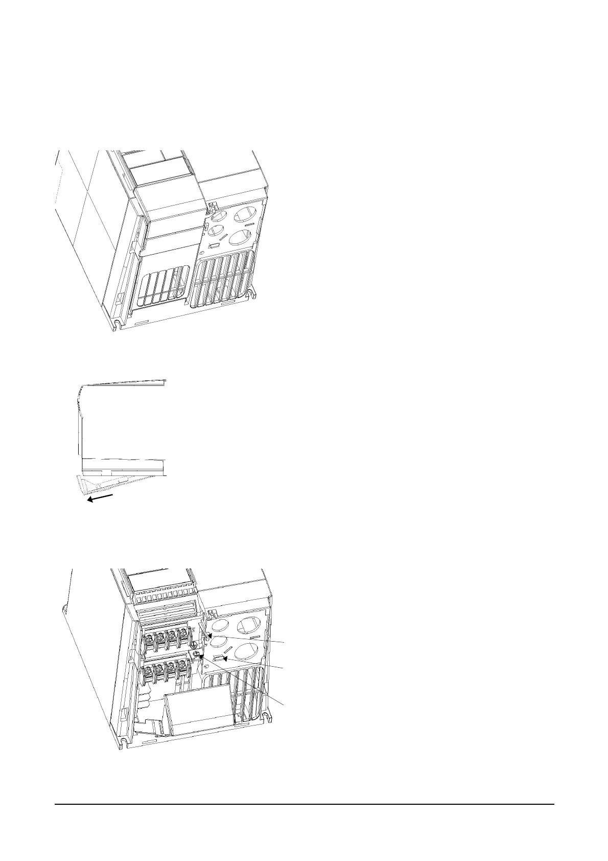
Power Connections Access Diagram - Frame Size B
Removal of Terminal Cover- Frame Size B
D
E
C
F
G
J
H
Figure 2.2.2 : Power and Motor Connectors MICROMASTER Vector Frame Size B
3. Remove the earthing screw C from the gland plate.
4. Press both release catches D and E to release the
gland plate and then remove the metal gland plate
from the inverter.
1. Insert the blade of a small screwdriver into slot A in the
front of the inverter and press in the direction of the arrow.
At the same time, press down on tab B at the side of the
access panel.
2. This will release the access panel, which will then swing
down on its rear-mounted hinges.
Note: The access panel can be removed from the inverter
when at an angle of approximately 30° to the horizontal. I
allowed to swing lower, the panel will remain attached to the
inverter.
F: Control cable input
G: Mains cable input
H: Motor cable output
J: Braking resistor/ DC link cable input