English 9. SUPPLEMENTARY INFORMATION
G85139-H1751-U529-D1 © Siemens plc 199
4/8/99
72
9. SUPPLEMENTARY INFORMATION
9.1 Application Example
Set-up procedure for a simple application
Motor: 230 V
1.5 kW output power
Application requirements: Setpoint adjustable via potentiometer 0 - 50 Hz
Ramp-up from 0 to 50 Hz in 15 seconds
Ramp-down from 50 to 0 Hz in 20 seconds
Inverter used: MMV150 (6SE3216-8BB40)
Settings: P009 = 2 (all parameters can be altered)
P080 - P085 = values given on motor rating plate
P006 = 1 (analogue input)
P002 = 15 (Ramp-up time)
P003 = 20 (Ramp-down time)
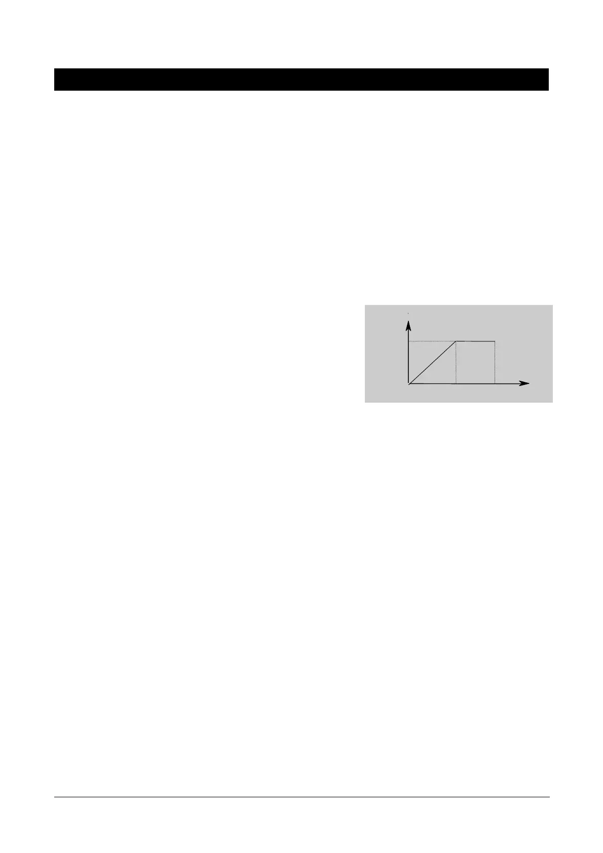
This application is now to be modified as follows:
Operation of motor up to 75 Hz
(voltage/frequency curve is linear up to 50 Hz).
Motor potentiometer setpoint in addition to
analogue setpoint .
Use of analogue setpoint at maximum 10 Hz.
Settings: P009 = 2 (all parameters can be altered)
P013 = 75 (maximum motor frequency in Hz)
P006 = 2 (setpoint via motor potentiometer or fixed setpoint)
P024 = 1 (analogue setpoint is added)
P022 = 10 (maximum analogue setpoint at 10 V = 10 Hz)
9.2 USS Status Codes
The following list gives the meaning of status codes displayed on the front panel of the inverter when the serial link is in use and
parameter P001 is set to 006:
001 Message OK
002 Slave address received
100 Invalid start character
101 Time-out
102 Checksum error
103 Incorrect message length
104 Parity fail
Notes
(1) The display flashes whenever a byte is received, thus giving a basic indication that a serial link connection is established.
(2) If ‘100’ flashes on the display continuously, this usually indicates a bus termination fault.
V
f (Hz)
220
50
75