English 2. INSTALLATION – MICROMASTER Vector
G85139-H1751-U529-D1 © Siemens plc 199
4/8/99
22
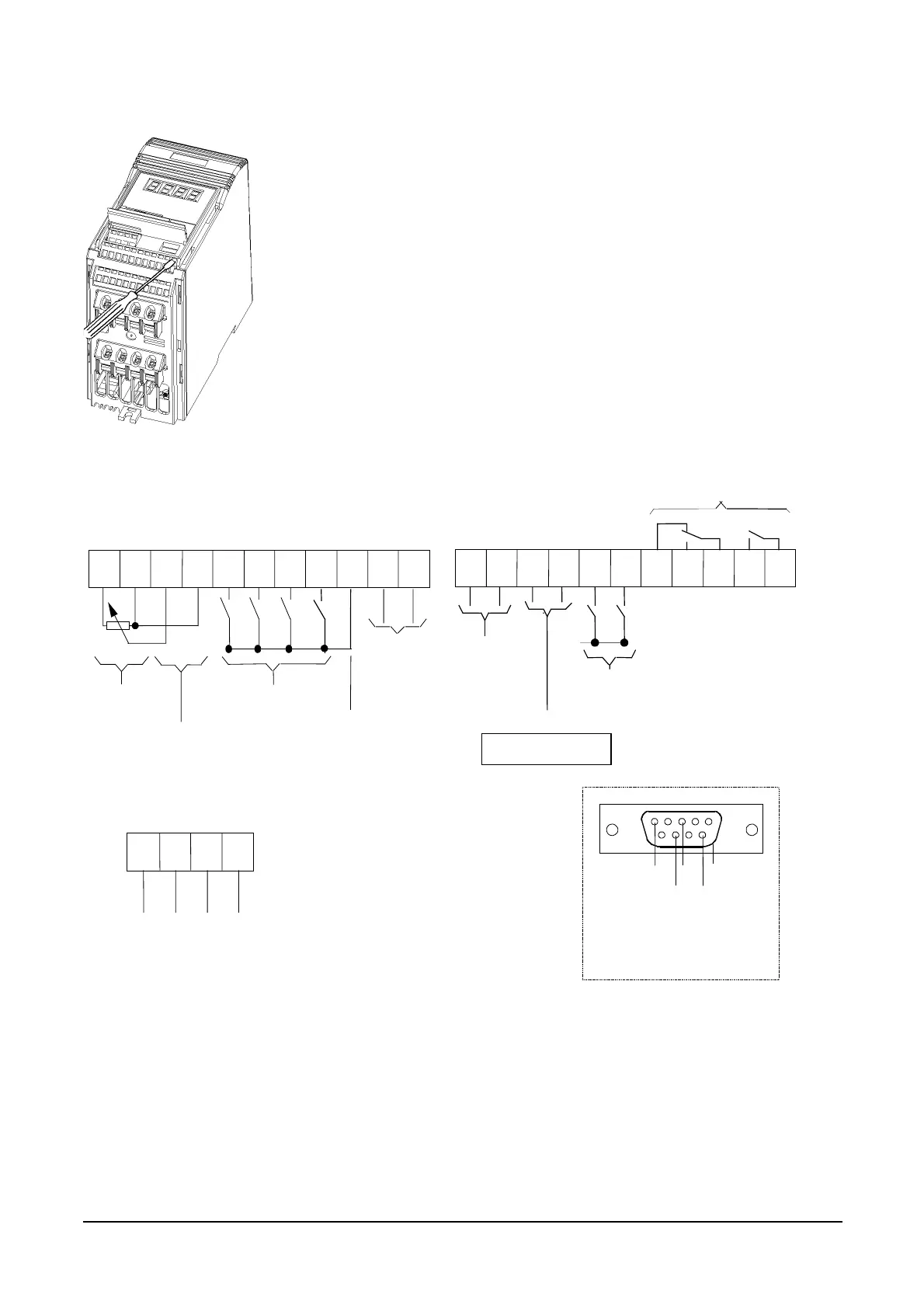
2.2.4 Control Connections
Output Rel ays
max. 2.0A / 110 V AC
0.8 A / 230 V AC
(overvoltage cat.2)
or
2A / 30 V DC
resistive ratin
Control Terminals
12 1
1
1
1
1
1
18 20
21
22
OUT+
OUT-
PT
PT
DIN
DIN6
Digital Inputs
(7.5 - 33 V, max.5 mA)
1234 85 6 7 9 10 11
Power Supply for
PID Feedback
Transducer
(+15 V, max. 50 mA)
Power Supply
(+10 V, max. 10 mA)
Analogue Input 1
-10 V to +10 V
0/2 Þ 10 V
(input impedance 70 k
W
)
or
0/4
Þ
20 mA
(resistance = 300
W
)
Digital Inputs
(7.5 - 33 V, max. 5 mA)
P10+ 0V
IN+
IN-
P15+
DIN1 DIN
DIN
PI DIN-
DIN4
PIDIN
Analogue input 2
0
Þ
10 V
or
0
Þ
20 mA
Analogue Output
0/4 - 20 mA
(500
W
load)
Motor temp. protection input
RL1A
(NC)
RL1B
(NO)
RL1C
(COM)
RL2B
(NO)
RL2C
(COM)
P+
PE
P5V+
N-
23 2
2
2
RS485
(for USS protocol)
Note: For PTC motor thermal
protection, P087 = 1
Front Panel
RS485 D-type
N-
0
5V
max. 250mA
P+
PE (case)
6
1
5
9
Figure 2.2.4: Control Connections - MICROMASTER Vector
Note: Do not use the internal RS485 connections (terminals 24 and 25) if you intend using the external RS485 connection on the
front panel e.g. to connect a Clear Text Display (OPM2).
DIP switches select between voltage (V) and current (I) analogue inputs and also select either a voltage or current feedback signal
(see Figure 4.1.2: DIP Selector Switches). These switches can only be accessed when the flap in the the front cover is raised (see
Figure 2.2.1).
Insert small blade screwdriver (max. 3.5 mm)
as shown, while inserting control wire from
below. Withdraw the screwdriver to secure
the wire.