7ML19985FF01 Milltronics MLC Belt Scale – INSTRUCTION MANUAL Page 5
Installation Procedure
1. Make sure the shipping stops are in place and secure.
2. Remove the existing flat roll idler (or flat slider pan) from the area selected to locate
the belt scale assembly.
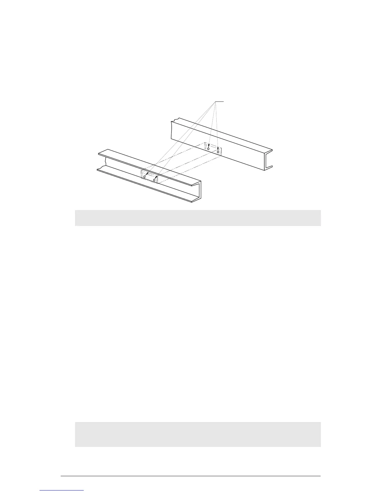
3. Drill four 12 mm (7/16") diameter mounting holes. This will allow clearance for 10 mm
(3/8") bolts.
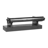
4. Position the scale with the idler towards the head end of the conveyor and the static
beam toward the tail end.
• Make sure the belt travel sticker on the static beam points in the direction of belt
travel.
• Raise the conveyor belting to provide room for the installation of the scale.
5. Insert the scale (complete with the attached idler) into the conveyor.
• Insert four 10 mm (3/8") bolts through the conveyor frame and through the holes
in the ends of the static beam.
• Secure with hex nuts. Finger tight only.
6. Make sure there is at least 13 mm (1/2") of clearance between the return belt and the
MLC.
• In some conveyors, it may be necessary to install a return idler roller adjacent to
the scale to deflect the return belt past the scale.
7. Position the scale so that it is centered in the conveyor and square to the stringer.
• Shim as required between the ends of the static beam and the conveyor
stringer.
• Level the static beam and tighten the bolts sufficiently to keep the static beam in
place until final adjustment.
Note: Slotting the holes vertically will permit greater adjustment capability.
CAUTION: Off-center or off-square installation can result in poor belt tracking and
scale inaccuracy.
12mm (7/16”)
(X 4)