MJ-X
L
Communications Module
7
12
J11
1
2
3
J10
J12
J14
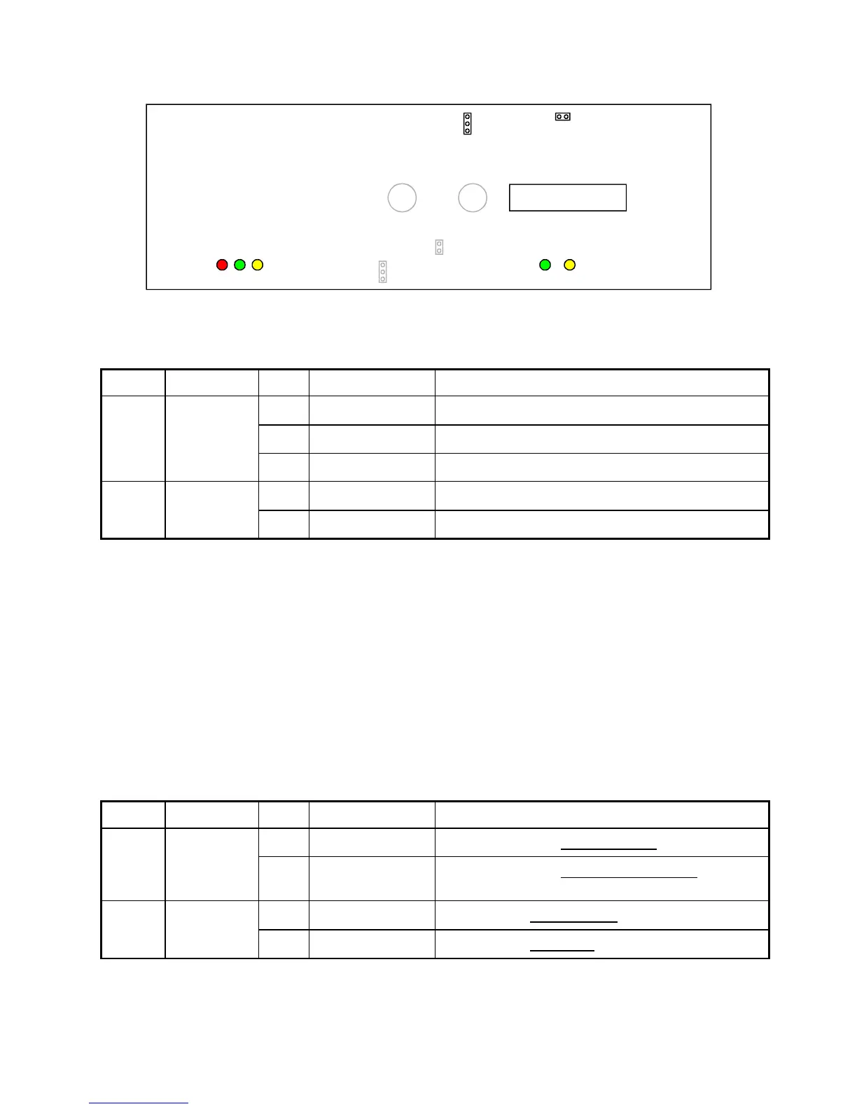
Figure 4-4 RS-232/485 Version Jumper Locations
Table 4-1 Fiber Optic Version Jumper Settings
Jumper Name Position Function Selected State Description
1-2
Auto Repeat Auto repeat for mark 0 or mark 1
2-3 No Repeat Force 0
J14 Auto Repeat
Out No Repeat Force 1 (no jumper installed at 1-2 or 2-3)
Out
Normal Set Low Power Transmitter OutputJ12 Range
In Long Set High Power Transmitter Output (See Note 2)
Note 1: Default pin settings are shown in bold text.
Note 2: If 50/125 µm cable is used, J12 must be jumpered (In). See section 5.1 for details.
4.3.2 RS-232/485 Version
Figure 4-4 shows the jumper locations on the RS-232/485 version, viewed from the component side. Jumpers and
their default settings are listed in Table 4-2.
In an RS-485 application, connect Signal Return (RTN) between the communication devices when there is a
ground potential rise between the connected devices. When the device RTN pins are connected, jumper J11 should
be Out (unless required by safety codes) to prevent ground loop currents. (If it is necessary to connect the RTN to
GND after the Communications Module is installed, you can make this connection at the 8-pin terminal block
connector with a wire jumper.)
Table 4-2 RS-232/485 Board Jumper Settings
Jumper Name Position Function Selected State Description
1-2 Receive Enable RS-485 receiver is always enabledJ10 RS-485
RCV EN
2-3
Auto Enable RS-485 receiver is automatically enabled by MJ-X
Communication Module microprocessor control.
Out
Not grounded Signal Return not connected to frame groundJ11 Safety
Ground Strap
In Grounded Signal Return connected to frame ground
Note: Default pin settings are shown in bold text.

 Loading...


