MJ-X
L
Communications Module
21
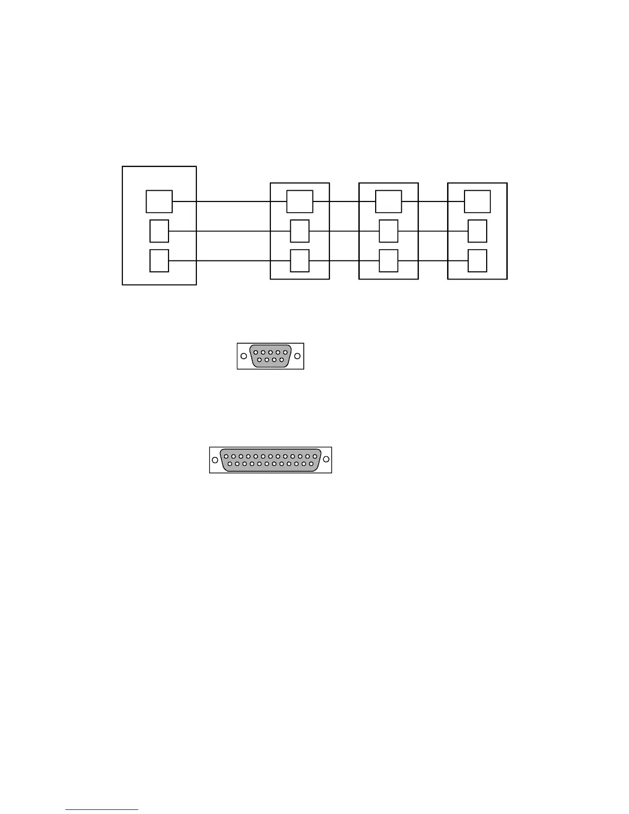
7.3.1 RS-232 Multi-drop Wiring
Multi-drop configurations require that the respective pins of the DTE devices be connected in parallel, Figure 7-7.
The standard pin assignments for RS-232 connectors are shown in Figure 7-8.
Note: For Figure 7-7, the RTU port is wired as “DTE”. When networking devices together, make sure the RTU
“data out” connects to the communications module Rxd, and the RTU “data in” connects to the communications
module Txd.
Signal
Return
Signal
Return
Signal
Return
Signal
Return
TX RX RX RX
RX TX TX TX
RTU MJ-X MJ-X MJ-X
Figure 7-7 RS-232 Multi-drop Configuration
1
1
6
9
5
13
14 25
Pin
1
1
2
2
3
3
4
4
5
5
6
6
7
7
8
8
20
9
22
*
*
*
Signal
Ground (Frame)
DCD
Txd
Txd
Rxd
Rxd
RTS
DTR
CTS
DSR
DSR
Ground (Signal)
Ground (Signal)
DCD
RTS
DTR
CTS
RI
RI
Shell (Frame Ground)
For Shielded Cable Connectors
Shell (Frame Ground)
DE9
DB25
Figure 7-8 RS-232 Connector Pinout
7.4 RS-232/485 Connections
The screw terminal block connector is keyed for proper insertion. Figure 7-9 shows the proper connector
orientation. Align the keys and insert the connector to interface to the RS-232/485 communications module.

 Loading...


