Connectable components
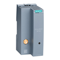
9.1 NX10.3 / NX15.3
NCU 7x0.3 PN
Manual, 09/2011, 6FC5397-1EP40-0BA0
87
Designs
CAUTION
The 80 mm ventilation spaces above and below the components must be observed.
An NX can be mounted in the control cabinet in the following ways:
NX on the side of the SINAMICS drive line-up
(Also refer to the Control Units Manual, supplementary system components, Chapter 2.4
"Installation").
First, you must insert the supports into the cutouts of the NX that are attached to the Line
Module. Then the NX can be attached to the Line Module.
NX with spacer directly on the rear panel of the control cabinet - standard
The NX is secured with two M6 screws (6 Nm) to the mounting panel.
NX without spacer directly on the rear panel of the control cabinet
In addition, you can secure the NX directly on the rear panel of the control cabinet even
without spacers. Using this method, you must remove the spacer attached as standard when
originally supplied.
Note
The spacer is secured with M3 torx screws on the NX. You require a screwdriver T10 to
attach/remove the spacer.
1. Removing the holding plate.
2. Remove the angle plate.
3. Attach the holding plate to the NX using M3 screws (0.8 Nm).
4. Attach the NX with two M6 screws (6 Nm) to the mounting panel.
Mounting an NX to an additional NX
For stability reasons, you can connect the bracket of one NX to the clip of an adjacent NX:
1. Open the interface covers.
2. Release the screw fixing the bracket.
3. The bracket must be moved so that the pin is in the opening of the bracket. Tighten the
screw.
4. Close the interface covers.
 Loading...