Bay Option Modules 9
For the
Data Adapter
, connect the data terminal equipment to
the 25-pin (EIA-232) connector on the back of the Data
Adapter. Reconnect the telephone line to the telephone.
For the
Headset Adapter
,
connect the headset to the headset
(RJ8) connector on the adapter. Reconnect the telephone line to
the telephone.
For the
Headset Plus Adapter
, connect the headset to the
headset (RJ8) connector on the adapter. Connect the recorder to
the recorder (RJ11) connector. Reconnect the telephone line to
the telephone.
For the
ISDN Adapter
, connect the ISDN terminal to the RJ45
adapter. Reconnect the telephone line to the telephone.
For the
Phone Adapter
, connect the secondary Optiset E
telephone into the RJ11 connector on the adapter. Reconnect the
telephone line to the telephone.
For the
Control Adapter
, connect the headset to the headset
(RJ8) connector on the adapter. Connect the PC from the serial
port on the PC to the (RS232) connector on the adapter.
Reconnect the telephone line to the telephone.
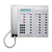
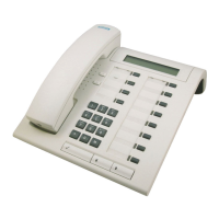
Optiset E Key Module
The side-mounted Optiset E Key Module adds 16 keys for
features and line appearances. Up to four Optiset E Key
Modules can be linked together on one telephone for a total of
64 additional feature keys and up to 29 line appearances. Only
the Optiset E Advance Plus and Memory telephones support
this option. Wall mount kits do not support telephones with an
Optiset E Key Module attached.
Figure 7. Optiset E Key Module
 Loading...