Accessories
7.2 Brake Relay
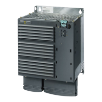
PM250 Power Module
68 Hardware Installation Manual, 09/2012, A5E01003502B AD
FSC
7.5 kW … 15 kW
FSD … FSF
18.5 kW … 90 kW
The Brake Relay control connector ① is on the
front of the Power Module. The Power Module
provides a cable duct
② for the control cable
The Brake Relay control connector
① is on the
bottom of the Power Module
Connecting the Brake Relay to the motor brake
%UDNH5HOD\
3RZHU0RGXOH
&75/
0
a
3RZHUVXSSO\
PRWRUEUDNH
Figure 7-8 Brake Relay connection
The Brake Relay has to be connected to protective earth, if the motor brake is supplied by a
PELV circuit.
Connecting the Safe Brake Relay to the motor brake
The Safe Brake Relay can only control motor brakes with 24V power supply.
6DIH%UDNH5HOD\
3RZHU0RGXOH
&75/
%5
9
9
0
0
%5
0
a
([WHUQDO
SRZHUVXSSO\
Figure 7-9 Safe Brake Relay connection
 Loading...